Direct Memory Access Using the HOLD Operation
4-29
Memory and I/O Spaces
Here are three valid methods for exiting the IDLE state, thus deasserting
HOLDA and restoring the buses to normal operation:
-
Cause a rising edge on the HOLD/INT1 pin when MODE = 0.
-
Assert system reset at the reset pin.
-
Assert the nonmaskable interrupt NMI at the NMI pin.
If reset or NMI occurs while HOLDA is asserted, the CPU will deassert HOLDA
regardless of the level on the HOLD/INT1 pin. Therefore, to avoid further con-
flicts in bus control, the system hardware logic should restore HOLD to a high
state.
4.7.1
HOLD During Reset
The HOLD logic can be used to put the buses in a high-impedance state at
power-on or reset. This feature is useful in extending the DSP memory control
to external processors. If HOLD is driven low during reset, normal reset opera-
tion occurs internally, but HOLDA will be asserted, placing all buses and con-
trol lines in a high-impedance state. Upon release of both HOLD and RS,
execution starts from program location 0000h.
Either of the following conditions will cause the processor to deassert HOLDA
and return the buses to a normal state:
-
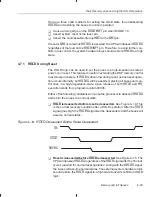
HOLD is deasserted before reset is deasserted.
See Figure 4–14. This
is the normal recovery condition after a HOLD operation. After the HOLD
signal goes high, the HOLDA signal will be deasserted, and the buses will
assume normal states.
Figure 4–14. HOLD Deasserted Before Reset Deasserted
RS
HOLD
HOLDA
-
Reset is deasserted before HOLD is deasserted. See Figure 4–15. The
CPU will deassert HOLDA regardless of the HOLD signal after the 16 clock
cycles required for normal reset operation. Along with the HOLDA signal,
the buses will assume normal states. The external system hardware logic
should restore the HOLD signal to a high state to avoid conflicts in HOLD
logic.


