background image

Eye


III+


Video Recording Transmitter


I

nstallation Guide


Page  64


Advanced Configuration - Modifying Settings


1.


Through Serial Port 


Step 1: 

Connect a shielded, straight-through 9-to-9 serial cable from the serial port of the computer 

to the 

AUX

 port of the 

VRB

.


Step 2: 

From Start menu, select 

Program Files   

Eye 

III+

   Transmitter Configuration

 to 

run the Configuration


program. Then, the Configuration program should appear. 
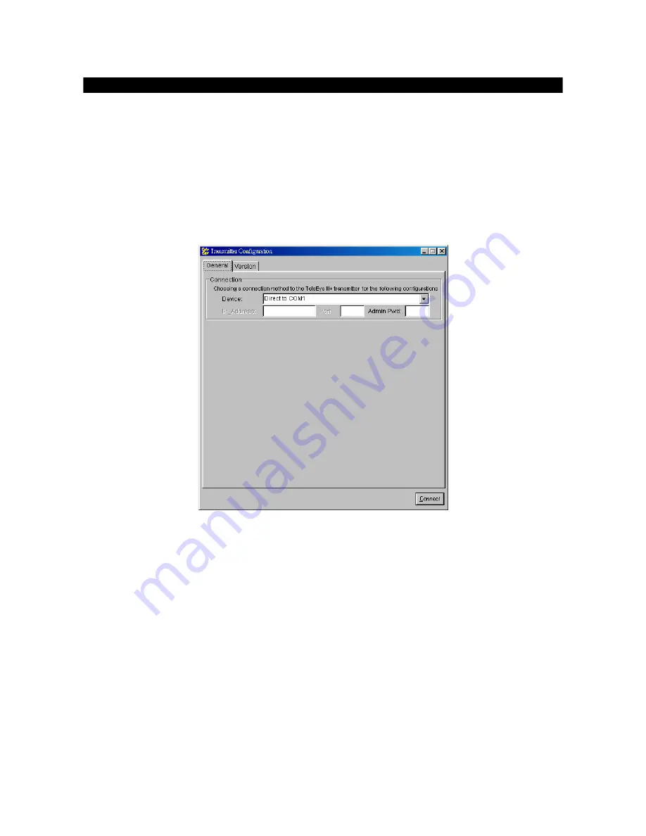
 

Step 3: 

Click on the 

General

 page. In the

 Connection 

group with

 Device

 menu,


choose the 

suitable serial port (COM1 or COM 2 or so on) for current connection to the transmitter. At 

the same time, enter the password in 

Admin Pwd

 field (The default one is 

“000000”

). 


Step 4: 

Click the 

Connect

 button. Please wait while it is connecting the transmitter. If 

Transmission 

unit not found!

 message is displayed, please check if the connection is correct, and you 

should close the configuration program and redo step 2. 


Step 5: 

Completed(

[baud rate]

)

 message box will be displayed. The transmitter default 

information will be displayed at each field. 


Step 6: 

Now you can make the necessary changes on fields provided. 


Step 7: 

After changing the settings, press 

Save and Exit

 button to write the information back to the 

transmitter. 


Step 8: 

Please wait until it shows 

Completed([

baud rate

])

 message box, where 

[baud rate]

 shows 

the serial port baud rate you are connecting between the PC and the transmitter.  

Summary of Contents for III+

Page 1: ...Video Recording Transmitter Installation Guide...

Page 2: ...ther countries All other trademarks are the property of their respective owners Copyright c 2005 Eye All rights reserved Version 1 01 Limits of Liability and Disclaimer of Warranty have taken care in...

Page 3: ...B 4041 6 Model VRB 8082 6 Model VRB 16164 7 Support BS8418 Model VRB 4041 8 Model VRB 8082 8 Model VRB 16164 9 Install Eye III VRB with Tamper Circuit and External Resistors 10 SECTION 3 GENERAL TERMS...

Page 4: ...with Static IP 32 C1 For Broadband Internet Connection with Dynamic IP using Router What you need 33 Transmitter Configuration 35 Router Configuration 39 Transmitter Installation 40 C2 For Broadband...

Page 5: ...ress Setup for Window NT 2000 61 Router Configuration 62 APPENDIX B ADVANCED CONFIGURATION MODIFYING SETTINGS Through Serial Port 64 Through Internet Intranet 65 Through Modem 66 APPENDIX C GLOSSARY 6...

Page 6: ...ement Powered by its proprietary video compression technology and remote accessibility VRB provides simultaneous remote monitoring recording and playback Users can keep track of live video and play ba...

Page 7: ...r PAL Up to 20fps on PSTN Excellent picture resolution up to 640 x 480 pixels 4 8 16 video alarm inputs Web based video monitoring Mobile video on Pocket PC Triplex Operation Simultaneous video monito...

Page 8: ...Eye III Video Recording Transmitter Installation Guide Page 3 Interface Description INTERFACE DESCRIPTION...

Page 9: ...is are recommended to be used ALARM SWITCH Port 4 remote control switches are available for all the models VRB 4041 4 alarm input ports VRB 8082 8 alarm input ports VRB 16164 16 alarm input ports All...

Page 10: ...number Definition Direction 1 CD Output 2 RXD Output 3 TXD Input 4 DTR Input 5 GND 6 DSR Output 7 RTS Input 8 CTS Output 9 N A MODEM Port A DB 9 male connector of DTE format capable for connecting to...

Page 11: ...3 N C Pin 15 RELAY 0a Pin 34 RELAY 0b Pin 16 RELAY 1a Pin 35 RELAY 1b Pin 17 RELAY 2a Pin 36 RELAY 2b Pin 18 RELAY 3a Pin 37 RELAY 3b Pin 19 N C For VRB 8082 model Pin 1 ALARM 1 Pin 20 GND Pin 2 ALARM...

Page 12: ...n 5 ALARM 5 Pin 24 GND Pin 6 ALARM 6 Pin 25 GND Pin 7 ALARM 7 Pin 26 GND Pin 8 ALARM 8 Pin 27 GND Pin 9 ALARM 9 Pin 28 GND Pin 10 ALARM 10 Pin 29 GND Pin 11 ALARM 11 Pin 30 GND Pin 12 ALARM 12 Pin 31...

Page 13: ...LARM 4 Pin 23 GND Pin 5 N C Pin 24 GND Pin 6 N C Pin 25 GND Pin 7 N C Pin 26 GND Pin 8 N C Pin 27 GND Pin 9 N C Pin 28 ARM DISARM Pin 10 N C Pin 29 SECURITY SWITCH Pin 11 N C Pin 30 POWER FAILURE Pin...

Page 14: ...34 RELAY 0b Pin 16 RELAY 1a Pin 35 RELAY 1b Pin 17 RELAY 2a Pin 36 RELAY 2b Pin 18 RELAY 3a Pin 37 RELAY 3b Pin 19 N C For VRB 16164 Pin 1 ALARM 1 Pin 20 GND Pin 2 ALARM 2 Pin 21 GND Pin 3 ALARM 3 Pi...

Page 15: ...with an alarm open condition when the system detected a 7 4k The transition from 1 2k to 7 4k is generated an alarm condition To set up the configuration of those alarms and input port are shown in th...

Page 16: ...edance 7K4 Term Status Description S C TAMPER Wire short point A and B LoZ NORMAL Switch close point B and C O C ALARM Switch open point B and C Term Status Description S C ALARM Switch close point A...

Page 17: ...9 5k Infinity DEOL Normal Close Tamper Short Normal Close Alarm Open Tamper Open DEOL Normal Open Tamper Short Alarm Close Normal Open Tamper Open SEOL Normal Close Tamper Short Normal Close Alarm N A...

Page 18: ...operation This setting should be configured during the installation of the transmitter For ideal performance in speed please choose the Speed option Note that you cannot set the video performance at t...

Page 19: ...Broadband with Dial up Software You have to choose one of the System Configuration Methods in later section to configure VRB before use so as to make it function properly The transmitter configuration...

Page 20: ...onvenient remote live video monitoring anytime and anywhere sureLINK Address You can apply for a sureLINK address domain name such as www hkpublic teleeye teleeye net for your transmitter You can use...

Page 21: ...to Apply for sureLINK Address You can apply for sureLINK by visiting our web site at http www TeleEye com Step1 Sign up to create your user account Step 2 Login the page using the your registered nam...

Page 22: ...processed Normally it requires about 2 to 3 working days to activate sureLINK for your transmitter You will receive a notification mail when your sureLINK service is ready Transmitter Modification Sin...

Page 23: ...nology Step 2 Enter the Old Registration Code New Transmitter Serial Number and New Registration Code at each field provided Click Modify button to submit the form If the above procedure is completed...

Page 24: ...Line Connection What You Need Hardware PC Minimum Requirement Pentium III 866 MHz Windows 95 98 ME XP NT or 2000 Operating System 128MB RAM VRB The video transmitter supports up to 4 8 16 video source...

Page 25: ...CE Data Computer Equipment serial cable The cable needs a DB 9 female connector for PC at one end and a DB 9 male connector for the AUX port of VRB at the other side Software Transmitter Configuration...

Page 26: ...Connect a shielded straight through 9 to 9 serial cable from the serial port of the computer to the AUX port of the VRB Step 2 Turn on the VRB A blue light at the front panel will flash continuously...

Page 27: ...nsmitter You will see all other fields are dim but Admin Pwd what you have to do is to provide an administrative password The default administrator password is 000000 Step 6 Before clicking the Connec...

Page 28: ...er s IP group with the default values Step 9 You can check the Enable to activate the Built in Web Server This makes you be able to see video through standard web browser Step 10 Ensure all settings a...

Page 29: ...nect the VIDEO OUTPUT of the CCD camera and VIDEO INPUT of the VRB CH1 is preferred If more than one camera are installed plug the BNC cables to the VRB CH2 to CH4 8 16 sequentially Step 6 Connect ala...

Page 30: ...he A C adapter to A C power source to power on the VRB The modem s LEDs ATA TR and VRB s LED on the front panel should light up Step 10 You may now use the Eye III Reception Software to connect to the...

Page 31: ...ources in all PAL or NTSC format PC Minimum Requirement Pentium III 866 MHz Windows 95 98 ME XP NT or 2000 Operating System 128MB RAM Power Adapter It is a 12 VDC power adapter supplied by Eye Group S...

Page 32: ...ROM WRS3 AD software Information Valid IP address for the transmitter Administrator Password for the transmitter The default administrator password is 000000 You can change it in the reception softwa...

Page 33: ...the AUX port of the VRB Step 2 Turn on the VRB A blue light at the front panel will flash continuously if it is successfully turned on Step 3 Install the VRB s Reception Software WRS3 AD from the CD...

Page 34: ...ord is 000000 Step 6 Before clicking the Connect button please make sure that the transmitter is well connected with your computer and it is switched on Or else a warning message Transmission unit not...

Page 35: ...Mode settings Step 10 You can Enable the Built in Web Server so that you can see video through web browser Step 11 Ensure all settings are correct then press the Save and Exit button Step 12 Please wa...

Page 36: ...the BNC cables to the Eye III Video Recording Transmitter CH2 to CH4 8 16 sequentially Step 5 Connect alarm sensor to the corresponding pins of the ALARM SWITCH port if necessary For the pin assignme...

Page 37: ...e Page 32 System Configuration and Installation B2 For Broadband Internet Connection with Static IP Please follow the step of B1 Internal LAN Access except you have to set the Gateway IP of your LAN w...

Page 38: ...sources in all PAL or NTSC format PC Minimum Requirement Pentium III 866 MHz Windows 95 98 ME XP NT or 2000 Operating System 128MB RAM Power Adapter It is a 12 VDC power adapter supplied by Eye Group...

Page 39: ...program installed included in the CD ROM WRS3 AD software Information Valid IP address for the transmitter Router IP address Please refer to your router menu Administrator Password for the transmitter...

Page 40: ...Connect a shielded straight through 9 to 9 serial cable from the serial port of the computer to the AUX port of the VRB Step 2 Turn on the VRB A blue light at the front panel will flash continuously i...

Page 41: ...ou have to do is to provide an administrative password The default administrator password is 000000 Step 6 Before clicking the Connect button please make sure that the transmitter is well connected wi...

Page 42: ...me subnet as that of the router please refer to your router setup menu to configure the router For example if your router s IP is 192 168 0 1 then the transmitter s IP can become 192 168 0 2 with subn...

Page 43: ...e Save and Exit button Step 14 Please wait until it shows Completed baud rate message box where baud rate shows the serial port baud rate for the communication between the PC and the transmitter Step...

Page 44: ...outer one That means if the router IP is 192 168 0 1 and subnet mask is 255 255 255 0 your PC s IP address must be 192 168 0 X where X is between 2 and 254 Example of Router Setting External port 1024...

Page 45: ...Step 5 Plug one end of the BNC cable into the VIDEO OUTPUT of the CCD camera then plug the other end to the VRB s VIDEO INPUT connector CH1 preferred If more than one camera are installed plug the BNC...

Page 46: ...he video transmitter supports up to 4 8 16 video sources in all PAL or NTSC format PC Minimum Requirement Pentium III 866 MHz Windows 95 98 ME XP NT or 2000 Operating System 128MB RAM Power Adapter It...

Page 47: ...smitter Configuration software A PC with Transmitter Configuration program installed included in the CD ROM WRS3 AD software Information Valid IP address for the transmitter Administrator Password for...

Page 48: ...VRB Step 1 Connect a shielded straight through 9 to 9 serial cable from the serial port of the computer to the AUX port of the VRB Step 2 Turn on the VRB A blue light at the front panel will flash co...

Page 49: ...t you have to do is to provide an administrative password The default administrator password is 000000 Step 6 Before clicking the Connect button please make sure that the transmitter is well connected...

Page 50: ...web browser Step 10 At the Gateway page leave the Gateway IP field as the default value 0 0 0 0 Step 11 At the sureLINK page Enable the sureLINK feature and enter the sub domain name should be regist...

Page 51: ...eld and 19001 for port field Step 13 Ensure all settings are correct then press the Save and Exit button Step 14 Please wait until it shows Completed baud rate message box where baud rate shows the se...

Page 52: ...you may now need to configure your Home PC NOT Remote PC You have to set a virtual IP for your computer for your local LAN We suggest the following data is to be set into your computer IP address 192...

Page 53: ...s that the transmitter cannot directly connected to the Internet without the help of the PC In this case you can install Eye Proxy Server software in PC and the PC will then become a bridge for the co...

Page 54: ...the Internet through Proxy Server Installed in PC Step 18 Click the Add button the new field will be added the list Keep open the program throughout the connection You will see a Eye Proxy icon on you...

Page 55: ...OUTPUT of the CCD camera then plug the other end to the VRB s VIDEO INPUT connector CH1 preferred If more than one camera plug the BNC cable to the VRB CH2 to CH4 CH8 CH16 sequentially Step 5 Connect...

Page 56: ...NABLED the Built in Web Server feature when configuring the transmitter For details please read Transmitter Configuration In your browser type http your sureLINK address e g http www hkpublic teleeye...

Page 57: ...on the left If your cameras have PTZ function you can see the ptz button on the web page For details on how to setup PTZ camera please refer to WRS AD Reception Software User Guide Auxiliary Port Setu...

Page 58: ...at the remaining normal videos can be seen It will be used in the following cases 1 Cannot playback the recorded videos 2 Cannot search the desired video from the recording log Or although you can fin...

Page 59: ...re scan your hard drive After connection has been made you can find the Hard Drive page In this page you can find the total size of the hard disk Capacity a percentage value showing the available size...

Page 60: ...ion Guide Page 55 Scan and Format the Hard Drive COMPLETE SCAN The time spent on scanning depends on the size of the hard disk Larger the hard disk is longer time it required When the scanning is comp...

Page 61: ...T As same as SCAN you can use Transmitter Configuration in the same folder as the WRS3 AD to format your hard drive After connection has been made you can find the Hard Drive page This time you have t...

Page 62: ...Format the Hard Drive COMPLETE FORMAT The time spent on scanning depends on the size of the hard disk Larger the hard disk is longer time it required After format the hard drive will have a clear and...

Page 63: ...C to get on the Internet If you discover that you cannot be able to access on the Internet after applying the settings you have to undo the settings or re install the software provided by your ISP and...

Page 64: ...oint to Point Protocol over Ethernet Note that the name of these two TCP IP adapters may be different on your computer You have to identify the purpose of each corresponding adapter Step 3 Choose TCP...

Page 65: ...Guide Page 60 Appendix Step 7 Select your Ethernet card name on the field you will see a IP address on the field Ensure that that is the same as you have set before i e 192 168 0 3 If it is not so ple...

Page 66: ...e Internet If you discover that you cannot be able to access to the Internet after applying the settings you have to undo the settings or re install the software provided by your ISP and retry the ste...

Page 67: ...tart run type cmd at Open field and pressed OK button then type ipconfig on the DOS prompt you will see a IP set on your computer Router Configuration Port Mapping in your Router For PLANET Internet S...

Page 68: ...to modify the transmitter settings By referring to which method you are currently connecting to the transmitter to view the video you can choose ONE of the methods below to make the changes Note that...

Page 69: ...e same time enter the password in Admin Pwd field The default one is 000000 Step 4 Click the Connect button Please wait while it is connecting the transmitter If Transmission unit not found message is...

Page 70: ...e same time enter the administrator password at the Admin Pwd field The default one is 000000 Step 5 Click the Connect button Please wait until it shows Read Process Completed Message box If Transmiss...

Page 71: ...nnect button Please wait while it is connecting the transmitter Step 5 A Completed baud rate message box will be displayed The transmitter default information will be displayed at each field Step 6 No...

Page 72: ...eillance zone However the delay time starts from the 1st trigger by the 1st alarm sensor i e Alarm4 The detailed procedure is as below 1 user turns off security switch 2 the alarm move to entry delay...

Page 73: ...be activated after the exit delay expires Fire Zone This zone will trigger alarm no matter what state the system is ie armed or disarmed It is suitable for installation of fire detectors Arm Disarm I...

Page 74: ...asynchronous 8 data bits 1 stop bit no parity 9 6k 115 2kbps hardware flow control AUX PORT RS 232C DB 9 female asynchronous 8 data bits 1 stop bit no parity 2 4k 19 2kbps hardware flow control RECORD...

Page 75: ...ale asynchronous 8 data bits 1 stop bit no parity 9 6k 115 2kbps hardware flow control AUX PORT RS 232C DB 9 female asynchronous 8 data bits 1 stop bit no parity 2 4k 19 2kbps hardware flow control RE...

Reviews: