


T3PSX3200P Series User Manual
40
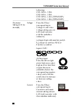
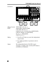
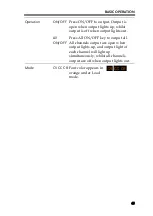
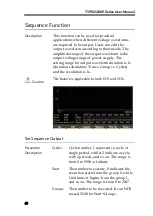
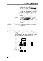
Output
The button ON/OFF of CH1/CH2 is individually
available, while All ON/OFF button is available
for all channels.
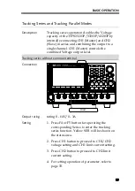
Tracking series with common terminal
Connection
0 - 32V , 3A
Memory
0 - 5V , 1A
CH3
CH2
CH1
ON/OFF
ON/OFF
Advance
CH3
ON/OFF
Lock
ALL
ON/OFF
Enter
8
5
2
9
6
3
PARALLEL OUTPUT
MASTER
0 - 32V , 3A
CH4
System
ON/OFF
CH2
GND
COM
SERIES OUTPUT
SLAVE
CH1
CH4
0 - 15V , 1A
0
7
4
1
T3PS43203P
Programmable DC Power Supply
32
V
3
A
+
-
com
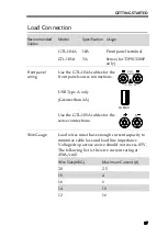
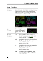
Load
Output rating
0 - 32V/0 - 3A for CH1+ - COM
0 - 32V/0 - 3A for CH2- - COM
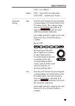
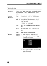
Operation
1.
Press F4 or F5 button for operating the
corresponding Series to enter the tracking
series function. Yellow SER will be shown on
the status area.
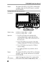
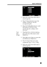
2.
Press CH1 button to proceed to CH1/CH2
voltage setting and CH1 limit current setting.
3.
Press CH2 button to proceed to CH2 limit
current setting.
4.
For setting operation of parameter, refer to
page 33.
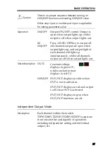
Output
The button ON/OFF of CH1/CH2 is individually
available, while All ON/OFF button is available
for all channels.
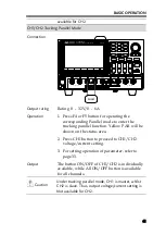
Caution
Under Tracking series mode, CH1 is master, whilst
CH2 is slave. Thus, output voltage setting is Not
Summary of Contents for T3PS13206P
Page 1: ... ...
Page 106: ...T3PSX3200P Series User Manual 106 Register Commands OPC 187 OPC 187 ...
Page 177: ...REMOTE CONTROL 177 Example SAV 1 Recalls the setting stored in memory 2 STATE02 ...
Page 185: ...REMOTE CONTROL 185 Example STB Returns 81 if the status byte register is set to 0101 0001 ...
Page 196: ...T3PSX3200P Series User Manual 196 Between chassis and DC power cord 30MΩ or above DC 500V ...
Page 197: ... 0 0 0 1 2 3 4 5 6 7 8 8 9 3 3 3 45 6 990 0 0 9 0 0 0 9 0 0 0 0 9 7 7 88 8 1 931711 RevB ...