


T3PSX3200P Series User Manual
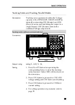
32
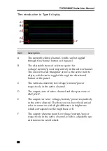
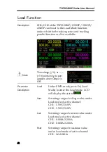
The introduction to Type 6 display
A
B
C
D
D
E
F
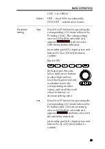
Item
Description
A
The currently edited channel, which can be toggled
through the channel button on the panel.
B
The adjustable items of reference point for
voltage/current/power respectively in the active channel.
The one with a red triangular arrow is the active item to
adjust, which can be toggled through the directional
button on the panel.
C
The vertical sensitivity for voltage/current/power
respectively in the active channel.
D
The output state of active channel and the open state of
OVP/OCP.
E
The output curve for voltage/current/power respectively
in the active channel. The three curves have the identical
color in common with slight difference in brightness,
which corresponds to the brightness of B.
F
The output reference point for voltage/current/power
respectively in the active channel, which is adjustable ups
and downs via scroll wheel.
Summary of Contents for T3PS13206P
Page 1: ... ...
Page 106: ...T3PSX3200P Series User Manual 106 Register Commands OPC 187 OPC 187 ...
Page 177: ...REMOTE CONTROL 177 Example SAV 1 Recalls the setting stored in memory 2 STATE02 ...
Page 185: ...REMOTE CONTROL 185 Example STB Returns 81 if the status byte register is set to 0101 0001 ...
Page 196: ...T3PSX3200P Series User Manual 196 Between chassis and DC power cord 30MΩ or above DC 500V ...
Page 197: ... 0 0 0 1 2 3 4 5 6 7 8 8 9 3 3 3 45 6 990 0 0 9 0 0 0 9 0 0 0 0 9 7 7 88 8 1 931711 RevB ...