Introduction
1- 18
1705A Spectrum Monitor
1705A
SPECTRUM MONITOR
IN
RF
OUT
HPA
OUT
IN
UP CONVERTER
OUT
VIDEO
EXCITER
70 MHZ
INPUT
DIRECTIONAL
COUPLER
RECEIVER
LNB
L-OUT
Ku-IN
Ku-BAND
14 GHZ
Ku-BAND
12 GHZ
3 dB
SPLITTER
L-BAND
900--1450 MHZ
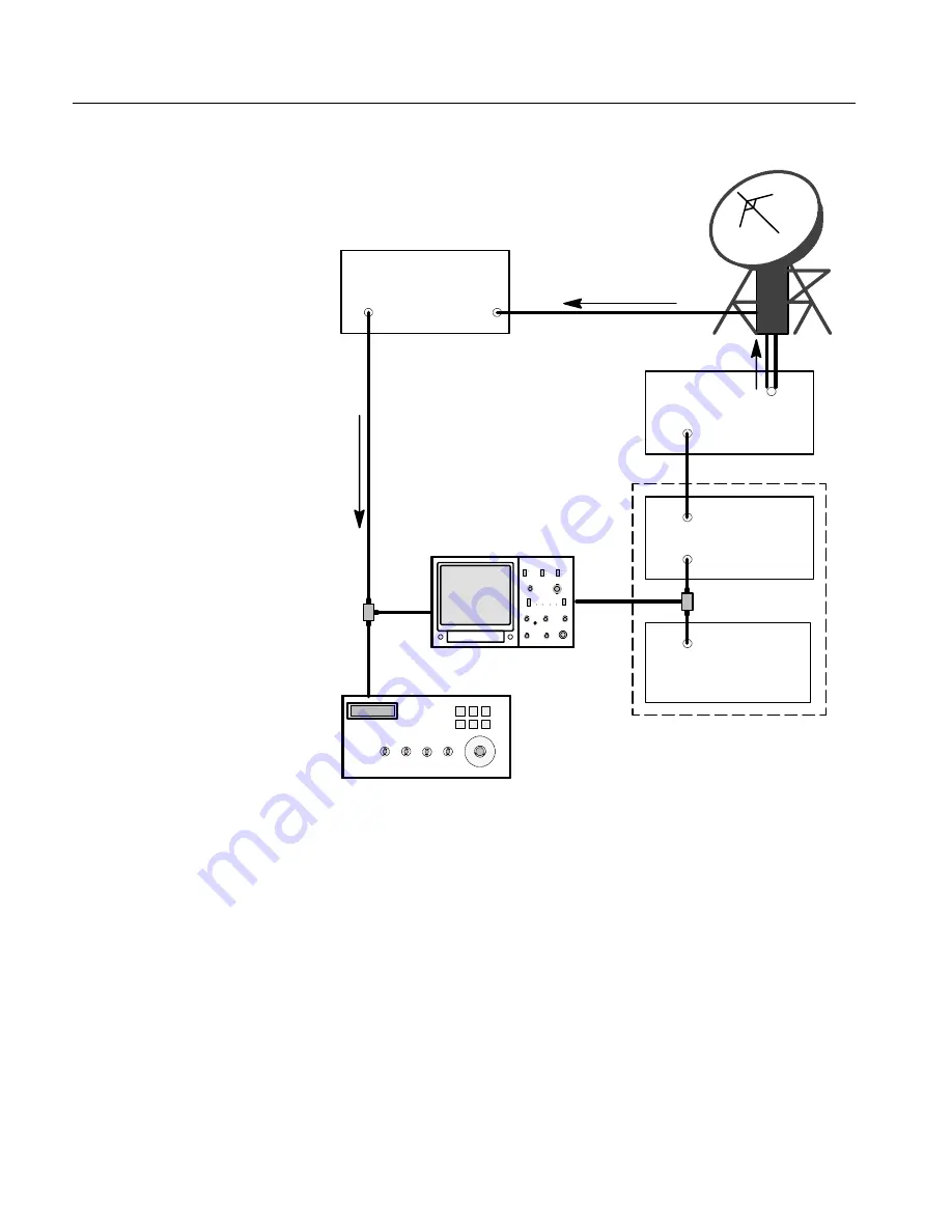
Figure 1-10: 1705A hooked up to look at either the output of the Video Exciter (70
MHz) or the Receiver Input (L-Band)
Summary of Contents for 1705A
Page 13: ...Service Safety Summary xii 1705A Spectrum Monitor ...
Page 17: ...Preface xvi 1705A Spectrum Monitor ...
Page 18: ...Introduction ...
Page 19: ......
Page 38: ...Operating Instructions ...
Page 39: ......
Page 61: ......
Page 62: ...Installation ...
Page 63: ......
Page 72: ...Theory of Operation ...
Page 73: ......
Page 93: ...Theory of Operation 4 20 1705A Spectrum Monitor ...
Page 94: ...Checks and Adjustments ...
Page 95: ......
Page 123: ...Checks and Adjustments 5 28 1705A Spectrum Monitor ...
Page 124: ...Maintenance ...
Page 154: ...Options ...
Page 155: ......
Page 158: ...Replaceable Electrical Parts ...
Page 159: ......
Page 189: ...Replaceable Electrical Parts 8 30 1705A Spectrum Monitor ...
Page 190: ...Diagrams Circuit Board Illustrations ...
Page 191: ......
Page 193: ......
Page 213: ......
Page 214: ...Replaceable Mechanical Parts ...
Page 215: ......
Page 223: ......


