


7-8
Sun Server X2-4 Service Manual • April 2013
7.6
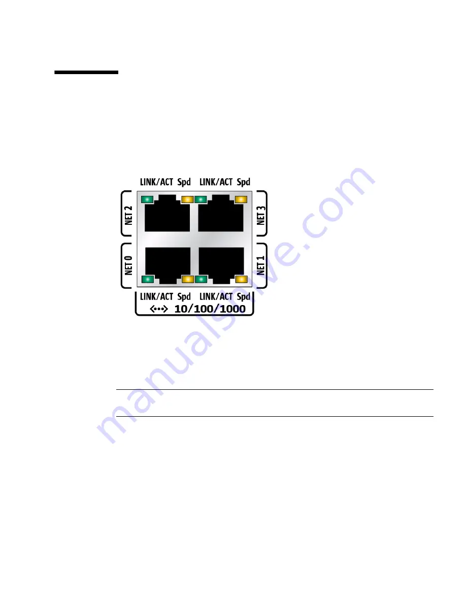
Ethernet Port Device and Driver Naming
The Sun Server X2-4 supports up to four 10/100/1000BASE-T Gigabit Ethernet ports,
located on the back of the chassis. The ports are labeled NET 0, NET 1, NET2, and
NET 3, as shown in
FIGURE 7-1
.
FIGURE 7-1
Ethernet Port Labeling Designations
The device naming for the Ethernet interfaces is reported differently by different
interfaces and operating systems. See
FIGURE 7-2
for a diagram that explains the
logical (operating system) and physical (BIOS) naming conventions used for each
interface. These naming conventions might vary depending on conventions of your
operating system and which devices are installed in the server.
Note –
Naming used by the interfaces might vary from that listed in
FIGURE 7-2
depending on which devices are installed in the system.
Summary of Contents for Fire X4470 M2
Page 1: ...Sun Server X2 4 formerly Sun Fire X4470 M2 Service Manual Part No E20784 06 April 2013...
Page 14: ...xiv Sun Server X2 4 Service Manual April 2013...
Page 38: ...2 12 Sun Server X2 4 Service Manual April 2013...
Page 54: ...3 16 Sun Server X2 4 Service Manual April 2013...
Page 84: ...4 30 Sun Server X2 4 Service Manual April 2013...
Page 106: ...5 22 Sun Server X2 4 Service Manual April 2013 FIGURE 5 11 Installing the Motherboard...
Page 153: ...Appendix A Server Specifications A 3...
Page 154: ...A 4 Sun Server X2 4 Service Manual April 2013...
Page 167: ...Appendix B BIOS Setup Utility Menus B 13 FIGURE B 16 BIOS PCIPnP Menu Second Screen...
Page 176: ...B 22 Sun Server X2 4 Service Manual April 2013...
Page 182: ...C 6 Sun Server X2 4 Service Manual April 2013...


