110
Netra t1 User and Administration Guide • June 2000
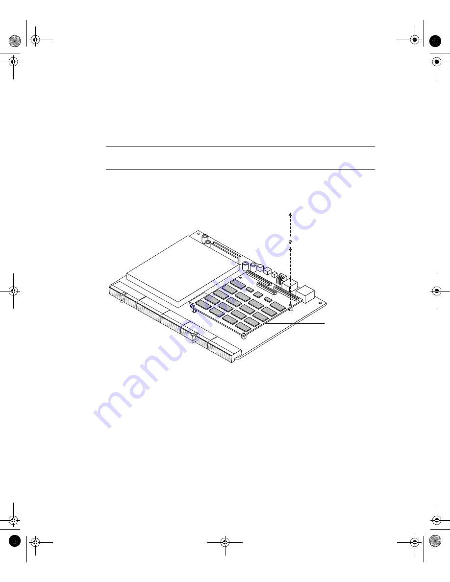
3. Using a Phillips No.1 screwdriver, remove the screws and washers from the base
memory board (see
If you intend to replace the base memory board, lift out the board that is currently
installed. Otherwise, leave the current board seated in the connectors on the
motherboard but not screwed in.
Note –
If you are making a 4-stack (1 Gbyte) configuration, the base board and all
other boards in the stack must be of part number 370-4155.
For purposes of illustration, the board you use as the base board will be called Board
A, Board B will be the board you put on top of Board A, Board C will be the one you
put on top of Board B, and Board D will be the one at the top of the stack.
FIGURE A-8
Removing the Mounting Screws from the Currently Installed Memory Board
4. If you are replacing the currently installed base memory board, align the
connectors of the new base board with the memory board sockets on the Netra t1’s
motherboard.
Press home fully the connectors using your thumbs. The connectors need to be
properly seated (see
). You might find it helpful to seat the middle
connector properly before the other two connectors.
Memory Board
Remove short screws
SysAdmin.book Page 110 Friday, March 30, 2001 2:38 PM
Summary of Contents for Netra t1 100
Page 21: ...PART I Installation and Configuration SysAdmin book Page 1 Friday March 30 2001 2 38 PM...
Page 22: ...SysAdmin book Page 2 Friday March 30 2001 2 38 PM...
Page 95: ...PART II Maintenance and Management SysAdmin book Page 73 Friday March 30 2001 2 38 PM...
Page 96: ...SysAdmin book Page 74 Friday March 30 2001 2 38 PM...
Page 121: ...PART III Appendices SysAdmin book Page 99 Friday March 30 2001 2 38 PM...
Page 122: ...SysAdmin book Page 100 Friday March 30 2001 2 38 PM...


