background image

81

6.1 

ヒューズの交換

1.  

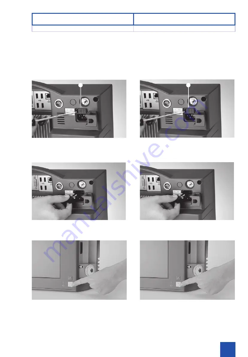
電源を切り、電源コードをコンセントから抜きます。


2.  

ドライバーを使用して、ヒューズホルダー

I

を外します。 


2

注意:

ヒューズを交換する際は、必ず正しい定格の

ヒューズを使用してください  

(電源ヒューズ:

2

 × 

T1.6AL250V

)。

3.  

新しいヒューズをヒューズホルダー

I

に挿入します。 

4. 


ヒューズホルダー

I

を再び本製品に取り付けます。


5.  

電源コードを再び接続し、電源をオンにします。


本製品の動作テストを行ってください。

6.1  퓨즈 교체

1. 

기기를 끄고 기기의 전원 장치를 분리합니다.


2. 

스크루 드라이버를 이용하여 퓨즈 홀더 

I

를 제거합니다.


2

주의:

 퓨즈를 교체할 때에는 정확한 규격의 퓨즈만 

사용하십시오(전원 퓨즈: 2 X T1.6AL250V).


3. 

새 퓨즈를 퓨즈 홀더

I

에 삽입합니다.


4. 퓨즈 홀더

I

를 기기에 다시 삽입합니다.


5. 

전원 장치를 다시 연결하고 기기를 켭니다.


이제 기기가 작동할 준비가 되었습니다. 기능 점검을 

수행하십시오.

18/01

I

I

6.1 

ヒューズの交換


6.1  퓨즈 교체

メンテナンス


6


유지보수

Summary of Contents for TECHNO PACK SP 100

Page 1: ...TECHNO PACK T LED Model SP 100 Instruction Manual...

Page 2: ......

Page 3: ...Instruction Manual TECHNO PACK T LED SP 100...

Page 4: ...3 Controls 20 3 1 Controls displays connectors and their uses 20 4 Getting started 24 4 1 Unpacking the device 24 4 2 Basic equipment 24 4 3 Overview of connections 26 4 4 Connecting the accessories...

Page 5: ...81 6 2 83 6 3 85 6 4 85 6 5 85 7 87 7 1 87 7 2 93 7 3 95 7 4 95 8 97 8 1 97 8 2 97 8 3 97 8 4 97 1 1 1 5 1 1 KARL STORZ 5 1 2 5 1 3 7 2 9 2 1 9 2 2 15 2 3 15 2 4 15 2 5 17 2 6 19 3 21 3 1 21 4 25 4 1...

Page 6: ...are possible for this reason Therefore no claims may be derived from the information figures and descriptions in this manual All product illustrations product descriptions and texts are the intellectu...

Page 7: ...TECHNO PACK T LED TECHNO PACK T LED KARL STORZ USB SD LED 3D Tip Curl 3 0 1 1 KARL STORZ KARL STORZ KARL STORZ KARL STORZ KARL STORZ SE Co KG 3 KARL STORZ SE Co KG 1 1 TECHNO PACK T LED TECHNO PACK T...

Page 8: ...nection Laser interface Color video camera USB connection SD SD card slot not active Line Out not active Line In not active Microphone input not active ACC not active Service interface Potential equal...

Page 9: ...7 1 3 USB SD SD ACC RoHS WEEE 1 3 USB SD SD ACC RoHS WEEE 2002 96 EC 18 01 1 3 1 3 1 1...

Page 10: ...operates 3 3 WARNING Test the system before each use to ensure that it is functioning correctly 3 3 WARNING Danger of an electric shock The device must only be connected to a correctly installed hosp...

Page 11: ...TECHNO PACK T LED 2 2 3 3 3 3 3 3 3 3 3 3 KARL STORZ 2 2 97 2 2 2 2 9 2 1 3 3 2 2 1 1 TECHNO PACK T LED 2 2 TECHNO PACK T LED 3 3 3 3 3 3 TECHNO PACK T LED 3 3 3 3 KARL STORZ KARL STORZ 2 2 97 2 2 2 2...

Page 12: ...ght cable 3 3 WARNING Risk of injury due to artificial optical radiation After measurement of its level of photobiological safety according to EN 62471 IEC 62471 the lamp system has been classified as...

Page 13: ...2 2 2 6 5 3 3 EN62471 IEC62471 1 EHV Exposure Hazard Value 1 13 HD Hazard distance 0 21m 4 3 3 3 3 1 1 LED 2 2 IEC 61010 1 IEC 60950 2 2 10 C 3 2 2 2 2 6 5 3 3 EN 62471 IEC 62471 1 EHV 1 13 HD 0 21 m...

Page 14: ...endoscope comes into contact with bare live parts Never touch live parts Disconnect the device from the mains disconnect the system from the power supply discharge capacitors etc 2 2 CAUTION Plugs an...

Page 15: ...13 3 3 2 2 1 1 3 3 2 2 1 1 18 01 2 1 2 1 2 2...

Page 16: ...nectors 2 3 Intended use The TECHNO PACK T LED is used for the endoscopic inspection of technical units e g turbines motors etc The basic unit is used for the power supply of the videoscope and displa...

Page 17: ...15 2 2 40 C USB 2 3 KARL STORZ 2 4 KARL STORZ 15 2 2 40 C 104 F USB 2 3 TECHNO PACK T LED TECHNO PACK T LED KARL STORZ TECHNO PACK T LED 2 4 KARL STORZ 18 01 2 2 2 2 2 3 2 3 2 4 2 4 2 2...

Page 18: ...ed to precipitation Operation in condensing atmospheres damp locations is not permitted 3 3 WARNING The product is not intended for use in potentially explosive atmospheres 2 2 CAUTION The device must...

Page 19: ...17 18 01 2 5 2 5 2 2 2 5 AC100 240 V 50 60 Hz 2 2 3 3 2 2 3000 m 2 2 2 2 10 cm 2 2 2 2 IEC 2 5 100 240V AC 50 60Hz 2 2 3 3 2 2 3000m 2 2 2 2 10cm 2 2 2 2 IEC...

Page 20: ...The exterior surfaces of the TECHNO PACK T LED can be cleaned with a cleaning agent suitable for surfaces that are sensitive to alcohol Recommendation Disposable cloth moistened with an ammonium chlo...

Page 21: ...19 2 6 TECHNO PACK T LED TECHNO PACK T LED 3 3 TECHNO PACK T LED 2 6 TECHNO PACK T LED 3 3 18 01 2 6 2 6 2 2...

Page 22: ...W E R 3 1 Controls displays connectors and their uses 3 Controls 3 1 3 3 1 Controls displays connectors and their uses Q On Off switch W Help button E Lateral connection panel 4 3 Overview of connecti...

Page 23: ...21 18 01 Q W R E 3 1 Q W E 29 R 3 1 Q W E 29 4 3 R 3 1 3 1 3 3...

Page 24: ...8 01 T U I O Y P 3 1 Controls displays connectors 3 Controls 3 1 3 T VESA 100 holder Y Potential equalization connector U Power cord socket I Fuse holder O Rear connection panel 4 3 Overview of connec...

Page 25: ...23 18 01 T U I O Y P T VESA 100 Y U I O 27 P T VESA 100 Y U I O 27 4 3 P 3 1 3 1 3 3...

Page 26: ...ort Remove the TECHNO PACK T LED and the accessories carefully from the packaging Check for missing items and evidence of shipping damage File any complaints immediately with the manufacturer or suppl...

Page 27: ...25 18 01 4 1 2 2 11 4 2 TECHNO PACK T LED 1 2 USB 1 1 1 USB 1 1 4 1 TECHNO PACK T LED TECHNO PACK T LED 2 2 11 4 2 1 TECHNO PACK T LED 2 1 USB 1 1 1 USB 1 4 1 4 1 4 2 4 2 4 4...

Page 28: ...Getting started 4 3 4 4 3 Overview of connections not active Line Out not active q Microphone input not active w Line In not active e not active r DVI Out external monitor t not active y 4 x USB u Se...

Page 29: ...27 18 01 y u w e q r t 4 3 q w e r DVI D t DVI D y USB 4 u 1 1 4 3 q w e r DVI t y 4 x USB u 1 1 4 3 4 3 4 4...

Page 30: ...x USB p A 18 01 i o p A 4 3 Overview of connections 4 Getting started 4 3 4 i SD card slot o 2 x USB p Laser interface Camera connector Connector for light cable A Light connector Retainer for unused...

Page 31: ...29 18 01 i o p A i SD o USB 2 p A i SD o 2 x USB p A 4 3 4 3 4 4...

Page 32: ...to connect a USB keyboard or a USB mouse Suggestion Use a combination of USB keyboard mouse here A list of supported storage media and hardware is available on request 1 Insert the USB device in one...

Page 33: ...31 18 01 4 4 USB USB USB 1 1 USB USB USB 1 USB USB y 27 USB SD 1 SD SD i 29 SD SD 4 4 USB USB USB 1 1 USB USB USB 1 USB USB y 27 USB SD 1 SD SD i SD 4 4 4 4 4 4...

Page 34: ...ut available on the rear of the device for connecting up an external monitor 1 Connect the monitor with the DVI D video output r 1 1 NOTE The connected monitor must support a resolution of 1024 x 768...

Page 35: ...33 18 01 DVI D 1 DVI D r 27 1 1 1024 768 XGA 2 DVI D 1 DVI D r 1 1 1024 x 768 XGA 2 TECHNO PACK T LED 4 4 4 4 4 4...

Page 36: ...ting plate 2 2 CAUTION This device may be operated only with the power cords provided by KARL STORZ or with comparable approved power cords 3 Connect the potential equalization cable with the TECHNO P...

Page 37: ...1 1 VESA 100 2 U 2 2 2 2 KARL STORZ 3 Y 2 2 1 1 1 A 1 1 KARL STORZ 4 5 1 1 1 VESA 100 2 U 2 2 2 2 KARL STORZ 3 TECHNO PACK T LED 2 2 TECHNO PACK T LED 1 1 1 TECHNO PACK T LED A 1 1 KARL STORZ 18 01 4...

Page 38: ...doscope twist the knurled screw on the screw base by a quarter turn 5 Switch the device on by pressing the button Connecting the videoscope 2 2 CAUTION The TECHNO PACK T LED basic unit must be switche...

Page 39: ...37 2 3 4 1 4 5 2 2 1 A 2 3 2 3 4 4 1 5 2 2 TECHNO PACK T LED 1 A 2 TECHNO PACK T LED 3 18 01 4 5 4 5 4 4...

Page 40: ...LED basic unit must be switched off when the laser box is inserted or removed 1 Insert the laser box of the videoscope as far as it will go into the light extraction socket A and connector 2 Insert t...

Page 41: ...39 2 2 1 A 2 p 3 4 2 2 TECHNO PACK T LED 1 A 2 TECHNO PACK T LED p 3 TECHNO PACK T LED 4 18 01 4 5 4 5 4 4...

Page 42: ...w dialog by pressing the Live View button 3 Switch the light source on by pressing the Light button 4 Open the settings window by actuating the Light intensity button 5 Select the desired light intens...

Page 43: ...41 1 1 1 USB USB 2 3 4 5 6 3 3 1 1 1 USB USB 2 3 4 5 6 3 3 18 01 4 5 4 5 4 4...

Page 44: ...menu and switches back to the previous menu Pressing the Up and Down arrow keys allows you to jump from one function button to the next 1 1 NOTE The following descriptions of the functions are based o...

Page 45: ...43 43 5 1 5 2 USB Enter ESC 1 1 2 2 2 2 3 2 3 ON OFF 2 1 1 ON OFF 5 1 5 2 USB ESC 1 1 2 2 1 2 3 3 2 1 18 01 5 1 5 1 5 2 5 2 5 5...

Page 46: ...educes increases the shutter if the space being examined is inadequately lit overlit Control is via the first and second button Camera head button 1 Laser intensity Control is via the first and second...

Page 47: ...45 2 3 2 1 2 1 1 2 3 5 3 1 1 2 2 3 2 1 2 1 1 2 5 3 1 1 18 01 5 3 5 3 5 5...

Page 48: ...ted only when a storage medium is available Available with more than one storage medium The device does not have any internal memory for user data which is why documentation data is stored on USB stor...

Page 49: ...47 2 GB USB SD 1 1 USB SD 1 USB SD 2 3 4 5 1 1 2 GB Disk 2 USB SD 1 1 USB SD 1 USB SD 2 3 4 5 OK 1 1 18 01 5 3 5 3 5 5...

Page 50: ...n be used to select one of the storage media The name of the storage medium and the projects contained on it will be displayed formatting in FAT32 required Safe removal of the storage medium In order...

Page 51: ...49 3 jpg mp4 jpg FAT32 1 1 1 1 KARL STORZ 1 1 3 jpg mp4 jpg FAT32 1 1 1 1 KARL STORZ 1 1 18 01 5 3 5 3 5 5...

Page 52: ...and function buttons of the Project contents view Project overview opens the project overview Project name Displays the selected project Camera Video Photo capture switches to Live View Change file na...

Page 53: ...51 5 4 5 4 18 01 5 4 5 4 5 5...

Page 54: ...cope or the camera Live image overview Overview of the function buttons Back Control shows the project contents Project name Display of the current project Storage medium Display of the selected stora...

Page 55: ...53 5 5 5 5 18 01 5 5 5 5 5 5...

Page 56: ...e function button saves a photo to the currently selected project If no project is selected then a project will be created by the software In the default setting the photo capture is saved under a nam...

Page 57: ...55 MP TIP 1 1 MP TIP 1 1 T 18 01 5 5 5 5 5 5...

Page 58: ...ns via a memory stick The adjustment data of the measurement lens used must be selected in order to perform an accurate measurement In the list select the used measurement lens along with the respecti...

Page 59: ...57 MP TIP 1 1 1 1 1 3 0 2 D T 1 1 1 1 1 3 0 D T 18 01 5 5 5 5 5 5...

Page 60: ...frame can be held and moved to the desired position The zoom window can be closed by clicking outside the window 5 7 Performing measurements The user can select between two measurement methods The me...

Page 61: ...59 5 6 1 1 4 2 3 5 6 x1 x1 4 x2 x3 5 7 3 0 3D 2D 5 7 2 Multipoint 3 0 3D 2D 18 01 5 6 5 6 5 7 5 7 5 5...

Page 62: ...s tools for editing the measurement image can be selected by means of function buttons If no other tool is selected then the selection tool will be automatically activated Elements can be selected wit...

Page 63: ...61 18 01 1 1 4 2 3 x1 x1 4 x2 x3 5 7 5 7 5 5...

Page 64: ...to eight different measurement types can be carried out Depth height length area and line to point measurements as well as 3D surface tip curl and blade clearance measurements Multipoint measurement a...

Page 65: ...63 3 0 TECHNO PACK T LED 3D 8 2 3D Tip Curl 49 3D 3D 1 1 TECHNO PACK T LED KARL STORZ 1 3 0 TECHNO PACK T LED 3D 8 3D 49 3D 3D 1 1 TECHNO PACK T LED KARL STORZ 18 01 5 7 5 7 5 5...

Page 66: ...del The measurement system suggests laser points for the definition of a mathematical model at which time the user can modify the model Every valid laser measurement point recognized by the system is...

Page 67: ...65 1 1 3D 3D 3D 1 1 X OK 18 01 5 7 5 7 5 5...

Page 68: ...measurement Area measurement Depth measurement 3D area tip curl and blade clearance measurements Multiline measurement Actuate the Extended measurement function button and select the Multiline measure...

Page 69: ...67 18 01 2 5 2 3D Tip Curl 3 OK 3 1 1 4 3D 3 OK 3 1 1 5 7 5 7 5 5...

Page 70: ...ct the button Point to Plane Point to Plane depth measurement In Point to Plane depth measurement the depth at an intersecting edge between two planes is measured by selecting two models Select a seco...

Page 71: ...69 18 01 2 2 OK 3D Tip Curl 2 2 2 2 2 2 1 1 1 1 2 Tip Curl Tip Curl 2 2 1 1 1 1 2 OK 3D 1 1 1 1 1 1 1 1 5 7 5 7 5 5...

Page 72: ...the reference measurement The reference measurement permits the determination of dimensions in a photo by means of a comparison with one of the reference dimensions you have specified You can determi...

Page 73: ...71 1 1 2 1 1 7 35 mm 1 1 1 1 1 1 TECHNO PACK T LED KARL STORZ mm inch 1 1 2 1 1 7 35mm 1 1 1 1 90 1 1 TECHNO PACK T LED KARL STORZ mm inch 18 01 5 7 5 7 5 5...

Page 74: ...d marking and label are shown in the photo Exit the function by clicking OK Modification of graphic properties It is possible to change both the color and the width of the lines of elements To accompl...

Page 75: ...73 OK 18 01 5 7 5 7 5 5...

Page 76: ...texts for videos and images etc can be made in this menu Overview of settings menu Overview of the function buttons Language Setting of the language Date time Setting of date and time Text overlay In...

Page 77: ...75 5 8 Text Overlay Logo Overlay MP TIP 5 8 18 01 5 8 5 8 5 5...

Page 78: ...se note that restarting is not necessary as of software version 3 0 Date and time This menu item can be used to set both the current date and the local time Text overlay It is possible to include a te...

Page 79: ...77 mm inch 1 1 3 0 png MP 5 7 mm inch 1 1 3 0 png 5 7 18 01 5 8 5 8 5 5...

Page 80: ...Select the desired data and import onto the device It is also possible to delete adjustment data that is no longer required 1 1 NOTE If adjustment data is deleted and the memory stick is not availabl...

Page 81: ...79 1 1 1 1 18 01 5 8 5 8 5 5...

Page 82: ...supply 2 Remove the fuse holder I using a screwdriver 2 2 CAUTION When replacing fuses use only fuses of the correct rating line fuse 2 x T1 6AL250V 3 Insert the new fuse into the fuse holder I 4 Pla...

Page 83: ...81 6 1 1 2 I 2 2 2 T1 6AL250V 3 I 4 I 5 6 1 1 2 I 2 2 2 X T1 6AL250V 3 I 4 I 5 18 01 I I 6 1 6 1 6 6...

Page 84: ...ive or from the manufacturer Safety check Regardless of the accident prevention regulations or testing intervals prescribed in different countries the following checks must be carried out on this devi...

Page 85: ...83 6 2 1 1 2 6 2 1 2 18 01 6 2 6 2 6 6...

Page 86: ...zed third parties 6 4 Servicing and repairs Defective items of equipment must be serviced and repaired exclusively by persons authorized by us all repair work must employ genuine KARL STORZ parts only...

Page 87: ...SE Co KG KARL STORZ KARL STORZ SE Co KG RoHS 6 3 3 3 KARL STORZ KARL STORZ KARL STORZ 3 6 4 KARL STORZ KARL STORZ 6 5 2002 96 EC waste electrical and electronic equipment WEEE KARL STORZ SE Co KG KAR...

Page 88: ...Remedy Check that there is electricity to the wall outlet Fit new fuse Push power cord connector firmly into device socket Send device to KARL STORZ for repair Error description No picture TFT flat sc...

Page 89: ...87 7 1 3 3 7 1 3 3 KARL STORZ TFT TFT KARL STORZ 18 01 7 1 7 1 7 7...

Page 90: ...TFT flat screen or camera Remedy Perform white balance Send device to KARL STORZ for repair Error description Color rendering alternates Possible causes Camera connecting cord is broken Remedy Send c...

Page 91: ...89 LED SD USB SD USB KARL STORZ TFT KARL STORZ KARL STORZ LED KARL STORZ USB 18 01 7 1 7 1 7 7...

Page 92: ...nt measurement Model not defined Remedy Set measurement method to match videoscope Select adjustment data of the lens used Check that videoscope plug fits firmly Define the model Error description Mea...

Page 93: ...91 KARL STORZ 18 01 7 1 7 1 7 7...

Page 94: ...C to 40 C atmospheric humidity 5 95 relative humidity air pressure 500 hPa 1080 hPa Storage temperature 10 C to 60 C atmospheric humidity 5 95 relative humidity Sound power level 50 dB A Degree of pr...

Page 95: ...500 K 20 000 TFT 15 1024 768 XGA 700 1 2 W USB 2 0 SD SDHC JPEG MPEG 4 PAL NTSC DVI D 3 5 mm 1 7 2 TECHNO PACK T LED 100 240V 50 60Hz 120W mm 450x350x150 7kg 10 C 40 C 5 95 500hPa 1080hPa 10 C 60 C 5...

Page 96: ...ompliance for SP 100 In accordance with EN IEC 61010 1 UL 61010 1 CAN CSA C22 2 No 61010 1 EN 60825 1 EN IEC 62471 Type of protection against electric shocks Protection Class I 7 4 Directive complianc...

Page 97: ...A C22 2 No 61010 1 EN 60825 1 EN IEC 62471 I 7 4 SP 100 CE LVD 2014 35 EC EMC 2014 13 EC 7 3 SP 100 EN IEC 61010 1 UL 61010 1 CAN CSA C22 2 No 61010 1 EN 60825 1 EN IEC 62471 I 7 4 SP 100 CE LVD 2014...

Page 98: ...camera heads 8 Spare parts accessories 8 1 8 2 8 3 8 4 8 8 1 Replacement parts list Article Order no Line fuse 1069500 Standard light adaptor 20045030 8 2 Compatible light cables All KARL STORZ light...

Page 99: ...L250V 1069500 20045030 8 2 KARL STORZ 8 3 KARL STORZ 8 4 TELECAM PAL NTSC TELECAM C PAL NTSC 8 1 1069500 20045030 8 2 KARL STORZ 8 3 KARL STORZ 8 4 PAL NTSC TELECAM SL DX 18 01 8 1 8 1 8 2 8 2 8 3 8 3...

Page 100: ......

Page 101: ...shipment The w arranty referred to in our Standard Conditions of Business shall apply KARL STORZ SE Co KG Postfach 230 D 78503 Tuttlingen KARL STORZ SE Co KG Postfach 230 D 78503 Tuttlingen Complete w...

Page 102: ...ress company stamp Field of application Type of instrument Serial no Purchase date Signature Date REPLY CARD KARL STORZ SE Co KG Postfach 230 78503 TUTTLINGEN GERMANY Please attach sufficient postage...

Page 103: ...e 30 2310 304868 Fax 30 2310 304862 E Mail info gr karlstorz com Repair Service Subsidiary KARL STORZ Industrial Gedik Is Merkezi B Blok Kat 5 D 38 39 Bagdat Cad No 162 Maltepe Istanbul Turkey Phone 9...

Page 104: ...78503 Tuttlingen Germany Telefon 49 0 7461 708 926 Telefax 49 0 7461 78912 E mail industrialgroup karlstorz com Internet www karlstorz com 01 2018 KARL STORZ SE Co KG 96196024EJCK 102 0071 2 7 2 8F P...

Reviews: