3-16
Installing the Servo Drive
07-01-08-02-E-V0500 631 Digital Servo Drive
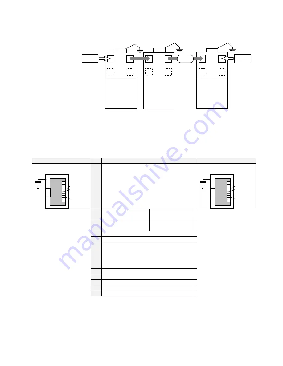
X20/21 - CAN-Bus Digital Interface Connections
Standard fieldbus protocol CAN-Bus interface.
631
631
NODE 2
LAST NODE
GND
GND
GND
631
NODE 1
X20
X21
X20
X21
X20
X21
124 Ohm
124 Ohm
CAN-Bus
Bus
Termination
Bus
Termination
To network several 631 servo drives, connect the X20/21 sockets as shown using the specified
cables. The 631 is configured using EASYRIDER software
<
.
Note:
The daisy-chain wiring is intended to be used for local bus distribution. Long bus
extensions should not cross daisy-chain sections.
Refer to Chapter 11: “Control and Communications” for cabling details.
X20
X20
X20
X20
Pin
Pin
Pin
Pin Function
Function
Function
Function
X21
X21
X21
X21
8-pole Modular Jack,
screened
1
8
CAN_GND
CAN_L
CAN_H
GND
CAN_GND
X20 and X21 are identically and internal
switched in parallel with all pins, (X20 = X21)
therefore bus-wiring is very easy.
8-pole Modular Jack,
screened
1
8
CAN_GND
CAN_L
CAN_H
GND
CAN_GND
internal connection to
GND via capacitor
Case: Screened
Operating Conditions
and Protocol
See documentation
7.5.3.x
1
11
1
2
22
2
3
33
3
CAN_GND
reference
galvanically separated.
Coupling-resistor to
PE / GND: 1M
Ω
4
44
4
CAN_L (dominant low)
5
55
5
CAN_H (dominant high)
6
66
6
7
77
7
CAN_GND, like Pin 3
8
88
8
This Pin Assignment is related to “CiA Draft Recommendation DR-303, V0.1 / 26.10.98”.
The wires on Pins 3/6 and 4/5 should be twisted pairs.
A defined quiescence level on the bus must be guaranteed for communication. You should use
terminal resistors on both ends of the line. Use special bus plugs that have a resistance of
approximately 124
Ω
between CAN_L and CAN_H.
Note:
A plug with an internal terminal resistor is available see Chapter 9: “Accessories”.


