2-2
An Overview of the Servo Drive
07-01-08-02-E-V0500 631 Digital Servo Drive
Control Features
POWER
X
2
1
X
4
1
X
2
0
X
4
0
X 3 0
X15/RS232
X
2
1
X
4
1
X
2
0
X
4
0
X 3 0
X15/RS232
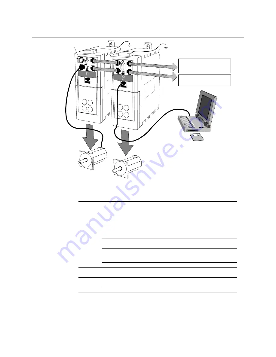
Resolver Connection
(mandatory)
Motor 1
Motor 2 (synchronised to Motor 1)
POWER
Encoder/Stepper connection
to next 631 controller
CAN-Bus connection
to next 631 controller
(last controller is terminated)
CAN-Bus terminator
EASYRIDER software
used to configure
each 631 individually
The Servo Drive is controlled via RS232, CAN-Bus or Incremental Bus using a PLC. It is
configured using the EASYRIDER software.
General
General
General
General
Operating Modes
Pulse/direction Input
±10V velocity control
Torue control
Position control
Encoder follower
Motion control
BIAS - motion language
CAM profiling
Setup, Service,
Programming
EASYRIDER software
Communications
Interfaces
CAN-Bus
RS232
Incremental Bus
Diagnostics
Diagnostic facility
Protection
Protection
Protection
Protection
Trip Conditions
Heatsink overtemperature and
Functions
Multiple protection functions - refer to Chapter 7
Inputs/
Inputs/
Inputs/
Inputs/
Outputs
Outputs
Outputs
Outputs
Inputs
±10V (12 bit) setpoint
4 In: 24V DC
Outputs
2 Out: 24V DC
Table 2-1 Control Features


