


88
(c) Spectrum Instrumentation GmbH
Buffer handling
Acquisition modes
Although an M4i is shown here, this applies to M4x and M2p cards as well. A data buffer handshake is implemented in the driver which
allows to run the card in different data transfer modes. The software transfer buffer is handled as one large buffer which is on the one side
controlled by the driver and filled automatically by busmaster DMA from/to the hardware FIFO buffer and on the other hand it is handled by
the user who set’s parts of this software buffer available for the driver for further transfer. The handshake is fulfilled with the following 3 soft
-
ware registers:
Internally the card handles two counters, a user counter and a card counter. Depending on the transfer direction the software registers have
slightly different meanings:
Directly after start of transfer the SPC_DATA_AVAIL_USER_LEN is every time zero as no data is available for the user and the SPC_DATA
-
_AVAIL_CARD_LEN is every time identical to the length of the defined buffer as the complete buffer is available for the card for transfer.
The counter that is holding the user buffer available bytes (SPC_DATA_AVAIL_USER_LEN) is related to the
notify size at the DefTransfer call. Even when less bytes already have been transferred you won’t get notice
of it in case the notify size is programmed to a higher value.
Remarks
• The transfer between hardware FIFO buffer and application buffer is done with scatter-gather DMA using a busmaster DMA controller
located on the card. Even if the PC is busy with other jobs data is still transferred until the application data buffer is completely used.
• Even if application data buffer is completely used there’s still the hardware FIFO buffer that can hold data until the complete on-board
memory is used. Therefore a larger on-board memory will make the transfer more reliable against any PC dead times.
• As you see in the above picture data is directly transferred between application data buffer and on-board memory. Therefore it is abso
-
lutely critical to delete the application data buffer without stopping any DMA transfers that are running actually. It is also absolutely criti
-
cal to define the application data buffer with an unmatching length as DMA can than try to access memory outside the application data
area.
• As shown in the drawing above the DMA control will announce new data to the application by sending an event. Waiting for an event is
done internally inside the driver if the application calls one of the wait functions. Waiting for an event does not consume any CPU time
and is therefore highly desirable if other threads do a lot of calculation work. However it is not necessary to use the wait functions and
one can simply request the current status whenever the program has time to do so. When using this polling mode the announced availa
-
ble bytes still stick to the defined notify size!
• If the on-board FIFO buffer has an overrun (card to PC) or an underrun (PC to card) data transfer is stopped. However in case of transfer
from card to PC there is still a lot of data in the on-board memory. Therefore the data transfer will continue until all data has been trans
-
ferred although the status information already shows an overrun.
• For very small notify sizes, getting best bus transfer performance could be improved by using a „continuous buffer“. This mode is
explained in the appendix in greater detail.
The Notify size sticks to the page size which is defined by the PC hardware and the operating system. There
-
fore the notify size must be a multiple of 4 kByte. For data transfer it may also be a fraction of 4k in the
range of 16, 32, 64, 128, 256, 512, 1k or 2k. No other values are allowed. For ABA and timestamp the notify
size can be 2k as a minimum. If you need to work with ABA or timestamp data in smaller chunks please use the
polling mode as described later.
The following graphs will show the current buffer positions in different states of the transfer. The drawings have been made for the transfer
from card to PC. However all the block handling is similar for the opposite direction, just the empty and the filled parts of the buffer are
inverted.
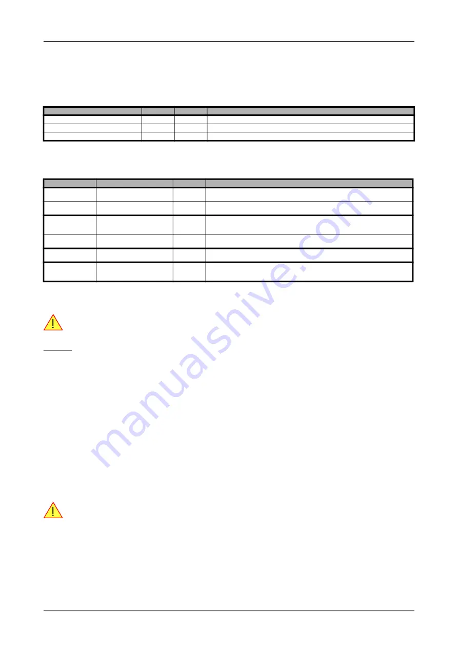
Table 40: Spectrum API: registers for DMA buffer handling
Register
Value
Direction
Description
SPC_DATA_AVAIL_USER_LEN
200
read
Returns the number of currently to the user available bytes inside a sample data transfer.
SPC_DATA_AVAIL_USER_POS
201
read
Returns the position as byte index where the currently available data samples start.
SPC_DATA_AVAIL_CARD_LEN
202
write
Writes the number of bytes that the card can now use for sample data transfer again
Table 41: Spectrum API: content of DMA buffer handling registers for different use cases
Transfer direction
Register
Direction
Description
Write to card
SPC_DATA_AVAIL_USER_LEN
read
This register contains the currently available number of bytes that are free to write new data to the
card. The user can now fill this amount of bytes with new data to be transferred.
SPC_DATA_AVAIL_CARD_LEN
write
After filling an amount of the buffer with new data to transfer to card, the user tells the driver with this
register that the amount of data is now ready to transfer.
Read from card
SPC_DATA_AVAIL_USER_LEN
read
This register contains the currently available number of bytes that are filled with newly transferred
data. The user can now use this data for own purposes, copy it, write it to disk or start calculations
with this data.
SPC_DATA_AVAIL_CARD_LEN
write
After finishing the job with the new available data the user needs to tell the driver that this amount of
bytes is again free for new data to be transferred.
Any direction
SPC_DATA_AVAIL_USER_POS
read
The register holds the current byte index position where the available bytes start. The register is just
intended to help you and to avoid own position calculation
Any direction
SPC_FILLSIZEPROMILLE
read
The register holds the current fill size of the on-board memory (FIFO buffer) in promille (1/1000) of
the full on-board memory. Please note that the hardware reports the fill size only in 1/16 parts of the
full memory. The reported fill size is therefore only shown in 1000/16 = 63 promille steps.
Summary of Contents for M2p.59 Series
Page 190: ......