40
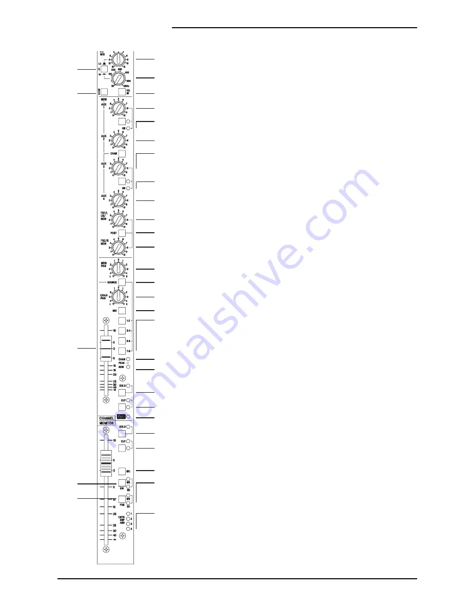
The Channel CUT switch is a soft switch, i.e. this switch provides an input to
the Automation. The Automation , in turn, controls the Cut circuit and also the
Channel CUT and Arm LEDs
41
The REC LED indicates when the tape machine is in record mode for the track
which is connected to this channel.
Monitor Path
42
The motorised Monitor Fader feeds the MON PAN control, it also feeds the
Aux1 and Aux2 Level controls and normally feeds the Aux3 and Aux4 Level
controls. It may also be switched to feed the FB1MON and FB2 buses.
43
A multi-point peak detector illuminates the MON PEAK LED when less than
6dB of headroom remains at two critical places in the signal path: the Monitor
Source switch and the pre-fade connection to the Monitor Fader.
44
The Monitor SOLO switch is a soft switch, i.e. this switch provides an input to
the Automation. The Automation , in turn, passes the Monitor signal onto the PFL
bus and also switches the input of the Control-room/Headphones circuit from its
selected input to the PFL bus.
The Automation also indicates, by switching on the associated SOLO LED, that the
Solo is active on the Monitor.
The Automation gives the Solo switch a toggle action: note that the switch itself
does not physically latch.
45
The Monitor CUT switch is a soft switch, i.e. this switch provides an input to
the Automation. The Automation , in turn, controls the Cut circuit and also the
Monitor CUT and Arm LEDs
46
The SEL switch is a soft switch, i.e. this switch provides an input to the
Automation. This switch has three functions.
Firstly, it is used to arm the Aux1, Aux3, Channel Cut and Monitor Cut switches.
To Arm one of these switches, you press and hold the SEL switch and then press
the CUT or Aux ON switch in question, then release both switches.
Secondly, it is used in conjunction with the Group Assignments pag. This allows
you to assign channels to Control Groups, see page 4.71.
Finally, if the RECORD ENABLE or PREVIEW modes are selected (via the control
panel keyboard) the SEL button may be used to Record Enable the tape track in
question. The REC LED indicates when this has happened.
Automated Fader and Switch Modes
Each Automated Fader and Switches can be in one of four modes, which are as
follows:
Manual.. The Fader or Switch operates normally as if it were not automated.
Read. Changes to the Fader or Switches which have previously been recorded
against the Timecode are played back, i.e. the changes are read from the Automation.
Armed. This mode is the same as Read mode until you make a change, at which
point the change(s) are written into the Mix Data.
20
21
23
24
25
26
27
28
27
29
31
30
32
36
33
35
34
38
39
40
41
44
45
46
48
49
43
19
22
37
42
47
4.8
DC2020 Mono Inputs
Summary of Contents for DC 2020
Page 1: ...SOUNDCRAFT USER GUIDE...
Page 6: ...iv DC2020...
Page 7: ...Introduction DC2020 Introduction 1 1...
Page 11: ...Installation DC2020 Installation 2 1...
Page 13: ...Assembling The Console Stand DC2020 Installation 2 3...
Page 35: ...Block Diagrams DC2020 Block Diagrams 3 1...
Page 36: ...Mono Input 3 2 DC2020 Block Diagrams...
Page 37: ...Stereo Input Groups DC2020 Block Diagrams 3 3...
Page 38: ...Aux Master 3 4 DC2020 Block Diagrams...
Page 39: ...Studio Foldback and Oscillator Talkback DC2020 Block Diagrams 3 5...
Page 40: ...Mix and Control Room Monitor 3 6 DC2020 Block Diagrams...
Page 41: ...Functional Descriptions DC2020 Functional Descriptions 4 1...
Page 42: ...4 2 DC2020 Functional Descriptions...
Page 43: ...Mono Inputs DC2020 Mono Inputs 4 3...
Page 51: ...Group Stereo Input DC2020 Group Stereo Input 4 11...
Page 55: ...Auxiliary Master DC2020 Auxiliary Master 4 15...
Page 58: ...4 18 DC2020 Auxiliary Master...
Page 59: ...Studio Outputs FB Masters DC2020 Studio Outputs FB Masters 4 19...
Page 63: ...Oscillator Talkback Panel DC2020 Oscillator Talkback Panel 4 23...
Page 66: ...4 26 DC2020 Oscillator Talkback Panel...
Page 67: ...Control Groups DC2020 Control Groups 4 27...
Page 70: ...4 30 DC2020 Control Groups...
Page 71: ...Stereo Master DC2020 Stereo Master 4 31...
Page 75: ...Control room Phones and Speakers DC2020 Control room Phones and Speakers 4 35...
Page 78: ...4 38 DC2020 Control room Phones and Speakers...
Page 79: ...Patchbay DC2020 Patchbay 4 39...
Page 80: ...Patchbay Fascia pbface eps 4 40 DC2020 Patchbay...
Page 87: ...Automation Guide DC2020 Automation Guide 4 47...
Page 88: ...4 48 DC2020 Automation Guide...
Page 89: ...Introduction DC2020 Introduction 4 49...
Page 94: ...4 54 DC2020 Introduction...
Page 95: ...Project Management DC2020 Project Management 4 55...
Page 100: ...4 60 DC2020 Project Management...
Page 101: ...The Automation Pages DC2020 The Automation Pages 4 61...
Page 152: ...4 112 DC2020 The Automation Pages...
Page 153: ...Automated Mixing DC2020 Automated Mixing 4 113...
Page 168: ...4 128 DC2020 Automated Mixing...
Page 169: ...Specifications DC2020 Specifications 5 1...
Page 172: ...5 4 DC2020 Specifications...
Page 173: ...Notes For Machine Control for Software Release 7 05 DC2020 Appendix A A 1...


