


Hydraulic connection
28
Installation manual
thermi
nator
II touch
Overall output of heat supply
German hard-
ness
Specific water content of the system <20 l / kW
≤ 50 kW
≤ 16.8 °dH
> 50 kW to ≤ 200 kW
≤ 11.2 °dH
> 200 kW to ≤ 600 kW
≤ 5.6 °dH
> 600 kW
≤ 2.8 °dH
Specific water content of the system ≥ 20 l/kW, but
< 50 l/kW
≤ 50 kW
≤ 11.2 °dH
> 50 kW to ≤ 200 kW
≤ 5.6 °dH
> 200 kW to ≤ 600 kW
≤ 2.8 °dH
> 600 kW
≤ 0.6 °dH
Specific water content of the system ≥ 50 l/kW
≤ 50 kW
≤ 5.6 °dH
> 50 kW to ≤ 200 kW
≤ 2.8 °dH
> 200 kW
≤ 0.6 °dH
In the event of exceeding the above values, the fill-up
water is to be treated. Recommended action: Soften-
ing (e.g., ion-exchange resin, the same procedure as
for drinking water softening).
Check the pH of the fill-up water
- In the normal case (mixed installation) no
measures are required to influence the pH (control:
value should be in the range of 8.2 to 10).
- Exception: If aluminium materials are used in the
heating system, a pH from 8.2 to 8.5 must be met
(pH> 8.5 increased corrosion tendency).
- If the value is significantly less than <8.2 after fill-
ing, then check again after 8-12 weeks
- If there is no increase in value, then add 10 g/m³
trisodium phosphate (Na3PO4) or 5 g/m³ sodium
hydroxide (NaOH).
Allow 2-4 weeks of operation before further correc-
tions.
Electrical conductivity
Recommendation: Low salt driving (filling with de-
mineralised water), see VDI 2035 sheet 2.
Low salt
Salty
Electrical conductivity
at 25°C
< 100
µS/cm
100
– 1500
µS/cm
Compliance with the above mentioned stand-
ards/regulations must be ensured by the heat-
ing engineer.
Manufacturer's requirements for high-efficiency
heat pumps: > The heater water must meet the
specifications of standard VDI 2035.
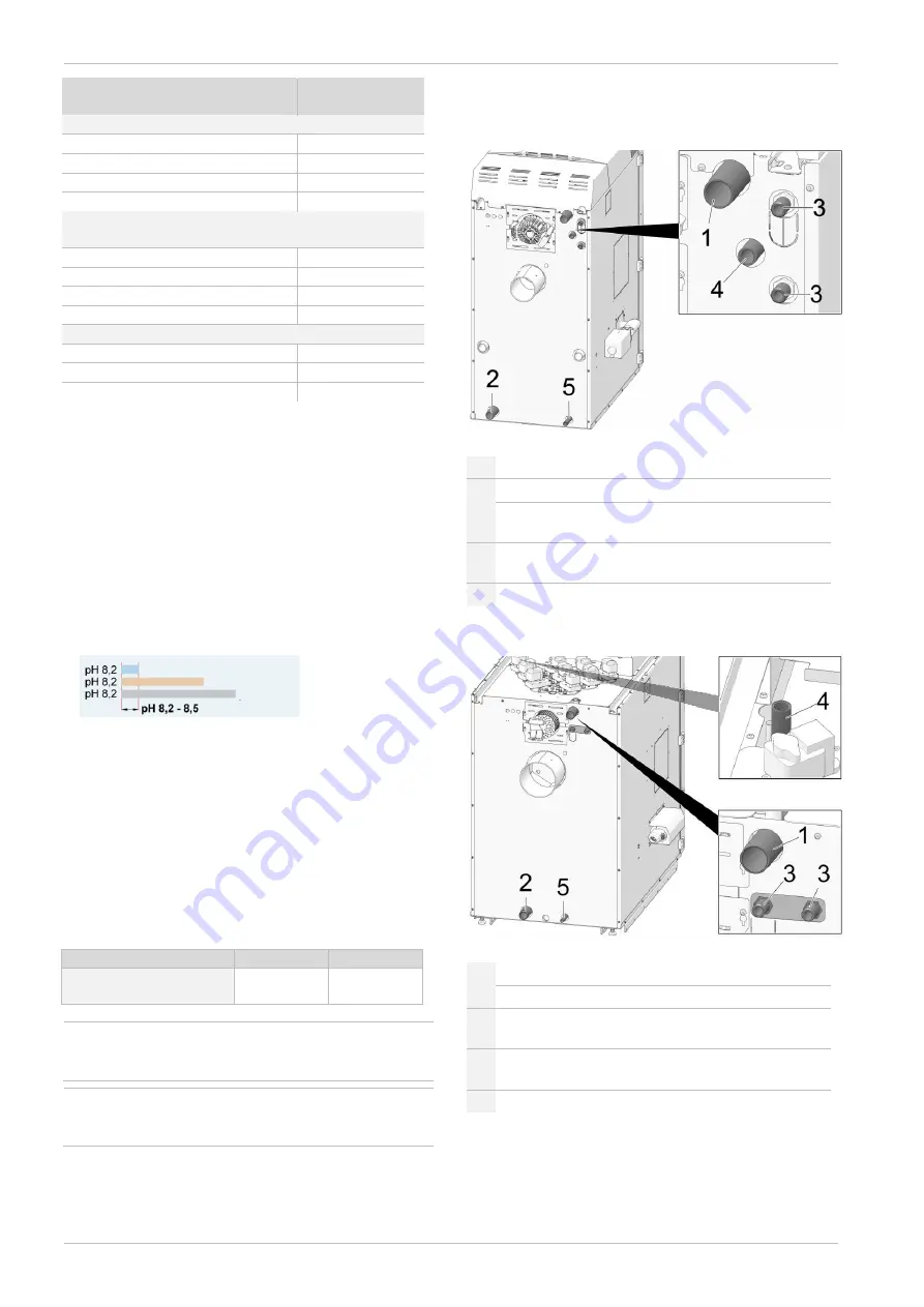
6.3 Boiler connections
thermi
nator
II 18 up to 30
Fig. 6-1_001cCP
1 Boiler flow
2 Boiler return
3
Connections for the thermal overload protection
(1/2” external thread)
4
Immersion sleeve for the sensor of the thermal
overload protection
5
Boiler drain point (1/2“ OT)
thermi
nator
II 36 up to 60
Fig. 6-2_002cBY
1 Boiler flow
2 Boiler return
3
Connections for the thermal overload protection
(1/2” external thread)
4
Immersion sleeve for the sensor of the thermal
overload protection (below the boiler cover)
5
Boiler drain point (1/2“ OT)
pH 8.5 Aluminium
pH 9.5 Copper
pH 10 Steel
Summary of Contents for Therminator II
Page 39: ...Annex Installation manual therminator II touch 39 9 6 Commissioning log ...
Page 40: ...Annex 40 Installation manual therminator II touch ...
Page 41: ...Annex Installation manual therminator II touch 41 9 7 Customer service order form ...
Page 42: ...Annex 42 Installation manual therminator II touch ...
Page 43: ...Annex Installation manual therminator II touch 43 ...


