background image

406388/B

153

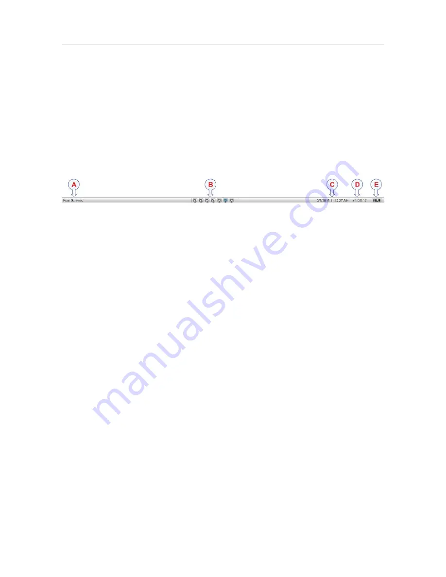
Bottom bar description

The bottom bar is located at the bottom of the TV80 presentation, and stretches from the far
left to the far right side. The function keys on the bottom bar correspond to the different
layouts defined in the

Load Layout

dialog box.

How to open

The bottom bar is available all the time.

Description

A

Name of layout

The name of the current layout in use is shown on the left side of the bottom bar. This
name changes automatically when you choose a different layout.

B

Function keys

The function keys on the bottom bar correspond to the different layouts defined in
the

Load Layout

dialog box. They provide fast access to the defined layouts of the

sensors views. You can have a maximum of twelve function keys. The function keys
are always available at the bottom bar of the TV80 presentation.

C

Date and time

The current date and time is shown on the right side of the bottom bar. During replay,
the date and time recorded with the data file are shown. The date is then shown with
prefix "R:" to indicate that a replay is in progress.

D

Software version

The current software version is always shown on the bottom bar of the TV80
presentation.

E

Keyboard

The on screen keyboard icon is shown on the right side of the bottom bar.

User interface

Summary of Contents for TV80

Page 1: ...Simrad TV80 Catch monitoring software TECHNOLOGY FOR SUSTAINABLE FISHERIES www simrad com Reference Manual...

Page 2: ......

Page 3: ...of this manual is to provide the descriptions and procedures required to allow for safe and efficient use of the Simrad TV80 The manual also offers a thorough understanding of the various TV80 operati...

Page 4: ...406388 B June 2018 Kongsberg Maritime AS...

Page 5: ...g the TV80 program 29 Turning off the TV80 30 Setting up summary 30 TV80 presentation overview 32 Starting normal operation 34 Adjusting the screen resolution 35 Introduction to the basic procedures 3...

Page 6: ...PI50 and PI60 Receiver Units on a serial line input 60 Defining the serial line communication parameters for the PI50 and PI60 Receiver Units 61 Selecting gear 62 Adding a new sensor 63 Creating a ne...

Page 7: ...02 Deleting and removing sensors 108 Removing one or more sensors from the system 108 Temporarily removing a sensor from the presentation 109 Configuring catch monitoring sensors 110 Configuring a PX...

Page 8: ...or data 135 Defining the folder settings for data recording 135 Accessing the saved data files 136 Recording sensor data 137 Selecting Replay mode 138 Resetting counters 140 Resetting the timer functi...

Page 9: ...menu 178 Load View dialog box 178 Edit View function 180 Designer module Functions and dialog boxes 181 Gauges dialog box 181 Edit Gauge dialog box 183 FUNCTIONS AND DIALOG BOXES 185 Main menu Functi...

Page 10: ...Filter function 219 Extras menu 221 View shortcut menu 222 Secondary functions and dialog boxes 223 New Layout 224 Edit Layout dialog box 225 Gear Setup dialog box 226 Add New Sensor dialog box 227 P...

Page 11: ...S 272 About NMEA and standard datagram formats 273 About the NMEA datagram formats 273 National Marine Electronics Association NMEA 273 NMEA sentence structure 274 Standard NMEA 0183 communication par...

Page 12: ...10 406388 B Simrad TV80...

Page 13: ...identify settings that will provide the best data at all times Careful study of the information in this manual is highly recommended preferably while exploring the TV80 functionality We assume that yo...

Page 14: ...mrad logo are either registered trademarks or trademarks of Kongsberg Maritime AS in Norway and other countries Windows is a registered trademark of Microsoft Corporation in the United States and othe...

Page 15: ...B 13 Introduction Topics Important page 14 System description page 15 Key features page 16 System diagram page 17 Main system units page 19 Network security page 23 Support information page 24 Introd...

Page 16: ...aks down If you believe that something has broken down contact your local dealer They will be able to assist A list of all our dealers is provided on our website https www simrad com If you are unable...

Page 17: ...g and navigation sensors The Simrad TV80 can receive information from the following catch monitoring systems Simrad PI32 Simrad PI44 Simrad PI54 Simrad ITI Simrad FS70 The Simrad TV80 can be connected...

Page 18: ...ed frequency band With this information you can identify noise and find the cleanest frequencies Related topics Key features page 16 System diagram page 17 Main system units page 19 Key features The S...

Page 19: ...I60 Receiver Units and the Processor Unit is made using a 1 1 serial line The communication between the SR70 and SR15 Receiver Units and the Processor Unit is made using a high speed Ethernet line The...

Page 20: ...ime These are commercial items that can be purchased locally Related topics System description page 15 Main system units page 19 Display description page 19 Processor Unit description page 20 PI50 60...

Page 21: ...e and with the correct height and angle Any commercial display can be used with the TV80 Catch monitoring software provided that the display meets the minimum requirements Tip Many computers offer two...

Page 22: ...power supply The PI50 PI60 Receiver Unit provides these interfaces Serial line cable to the Processor Unit One hydrophone External power supply Related topics Main system units page 19 System diagram...

Page 23: ...out any need of switches or splitters The SR70 Receiver Unit operates on 110 to 230 VAC A high quality Ethernet cable connects the SR70 Receiver Unit to the Processor Unit The distance between the Pro...

Page 24: ...a 50 meter integrated cable The cable is supplied on a reel for convenient retrieval and stowage and is equipped with a plug for easy attachment to the Sensor Receiver The cable is sheathed in polyur...

Page 25: ...his Kongsberg Maritime has no information regarding the complete system installation on any vessel Systems provided by Kongsberg Maritime are regarded as stand alone offline systems They are stand alo...

Page 26: ...0 Horten Norway Telephone 47 33 03 40 00 Telefax 47 33 04 29 87 Website https www simrad no E mail address simrad support simrad com Spain Company name Simrad Spain S L U Address Partida Atalayes 20 0...

Page 27: ...laysia Telephone 65 6411 7488 Telefax 60 3 2201 3359 Website https www simrad com E mail address simrad asia simrad com Korea Company name Kongsberg Maritime Korea Ltd Address 1101 Harbor Tower 113 1...

Page 28: ...26 406388 B Related topics Important page 14 Simrad TV80 Reference Manual...

Page 29: ...Turning the TV80 on and off page 29 Setting up summary page 30 TV80 presentation overview page 32 Starting normal operation page 34 Setting up the TV80 Catch monitoring software for the first time pag...

Page 30: ...installed The following software tasks are relevant 1 Install the TV80 software 2 Apply the licence key 3 Select and set up each sensor receiver you wish to use 4 Select and set up each catch monitor...

Page 31: ...ructions provided by the display manufacturer 2 Turn on the Processor Unit Wait for the operating system to start up 3 On the Processor Unit desktop double click the TV80 icon to start the program 4 S...

Page 32: ...manually 3 Turn off the display If required refer to the instructions provided by the display manufacturer 4 If relevant power off each sensor receiver The sensor receiver is normally not fitted with...

Page 33: ...onal software 3 On the Software License page install the software license s 4 Connect the Receiver Unit to the Processor Unit 5 Set up the SR70 Receiver Unit SR15 Receiver Unit in the TV80 application...

Page 34: ...sy access to all the functionality offered by the TV80 A Top bar The TV80 top bar is located on the top of the display presentation and stretches from the far left to the far right side It provides bu...

Page 35: ...presentation On the top bar use the Menu button to hide or show the menu F Secondary menus The bottom of the Main menu holds the icons to open and close the secondary menus Select an icon to open the...

Page 36: ...ceiver Units on a serial line input page 40 Defining the serial line communication parameters for navigation sensors and external devices page 41 Defining receiver parameters for the PI50 and PI60 Rec...

Page 37: ...re detailed information The physical width of your top bar will also be extended and free space for icons and navigational information Unless you change the hardware computer graphic adapter or displa...

Page 38: ...used it If these settings are acceptable continue operation Selecting menu language You may prefer to use the TV80 with a user interface in your own language The Language function allows you to selec...

Page 39: ...you to control which units of measurements that are used Context The TV80 user interface presents many measurements These measurements are for example related to depth speed or temperature Use the Un...

Page 40: ...ic amplitude range All targets are correctly measured and displayed The SR15 Receiver Unit allows you to connect one single hydrophone Depending on your fishing requirements you may need to install mo...

Page 41: ...equirements must be met The TV80 software is installed on the Processor Unit The license string for the software is installed and activated One or more receivers are available for connection to the TV...

Page 42: ...a critical error since many systems have proprietary NMEA datagram sentences that are not used and therefore do not need decoding Setting up the PI50 and PI60 Receiver Units on a serial line input In...

Page 43: ...bout the connection Defining the serial line communication parameters for navigation sensors and external devices Serial line communication is important for TV80 operation All serial line communicatio...

Page 44: ...I50 and PI60 Receiver Units The Receiver dialog box allows you to set up the detailed parameters for the signal reception It allows you to fine tune the receiver for optimal performance Sea conditions...

Page 45: ...rmation the TV80 needs to communicate with external devices In order to communicate with peripheral devices the Processor Unit offers several serial and or Ethernet LAN ports In the Add LAN Port dialo...

Page 46: ...Add LAN Port to open the Select Input LAN dialog box 6 Select the system you want to interface from the list provided Every interface is presented as a small block diagram Note Just adding an external...

Page 47: ...sically connected to the TV80 using a serial or network cable The interface port is set up with the correct communication parameters Context The serial line connection can provide information from the...

Page 48: ...rs and close the Serial Port Setup dialog box 9 Repeat for each sensor interface that you need to set up Checking the data transfer on a serial line The communication between the Processor Unit and pe...

Page 49: ...must be active and transmitting information to the TV80 If the data flow is not present we suggest the following actions Check that the peripheral system has been switched on Check that the peripheral...

Page 50: ...s presented as a small block diagram 4 Select the inspection point at the left of the block diagram you want to check The Measurements dialog box opens 5 Check if the TV80 is receiving information fro...

Page 51: ...y the Record function Prerequisites Before you start data recording make sure that you have defined where to store the files To define which disks and folders to use to save the data files use the Fil...

Page 52: ...circle on the right side of the button The Record button on the top bar changes colour to reflect that recording is active 3 To stop recording open the Record button and select Off Alternatively simpl...

Page 53: ...eters for the PI50 and PI60 Receiver Units page 61 Selecting gear page 62 Adding a new sensor page 63 Creating a new sensor view page 65 Creating a TrawlEye view page 67 Inspecting the receiver qualit...

Page 54: ...se 8 Select one or more catch monitoring sensors and place them on the chosen gear 9 Open the Receiver dialog box to define the parameters related to reception such as filter and gain 10 Open the Meas...

Page 55: ...operties on the short cut menu g On the list of connections select Internet Protocol 4 TCP IPv4 and then Properties This procedure is made for the Microsoft Windows 7 operating system a In the bottom...

Page 56: ...e 1 Turn on the Processor Unit 2 Insert the software media If the software is provided on a CD or DVD and your Processor Unit is not fitted with a suitable drive copy the files to a USB flash drive 3...

Page 57: ...structions provided by the display manufacturer 2 Turn on the Processor Unit Wait for the operating system to start up 3 On the Processor Unit desktop double click the TV80 icon to start the program 4...

Page 58: ...tly Note Once you receive your software license string do not lose it We suggest that you copy the information into a text file for example Notepad and add relevant information Place the text file on...

Page 59: ...sor Unit using an Ethernet line Prerequisites In order to connect a catch sensor to the TV80 system the following requirements must be met The TV80 software is installed on the Processor Unit The lice...

Page 60: ...to identify the quality of the information that is received When an inspection point is green the information is properly received When an inspection point is red it means that a specific datagram is...

Page 61: ...g box opens 3 Observe the I O Setup page on the right side of the Installation dialog box 4 Select Add LAN Port Observe that the Select Input LAN dialog box opens 5 Select the SR70 Receiver Unit Every...

Page 62: ...ine Procedure 1 Open the Setup menu 2 On the Setup menu select Installation Observe that the Installation dialog box opens 3 Observe the I O Setup page on the right side of the Installation dialog box...

Page 63: ...ocessor Unit using a serial cable Procedure 1 Open the Setup menu 2 On the Setup menu select Installation Observe that the Installation dialog box opens 3 Observe the I O Setup page on the right side...

Page 64: ...fishing gear profile for every net will help you save a lot of time and efforts whenever you change operations Procedure 1 On the Setup menu select Installation Observe that the Installation dialog b...

Page 65: ...em and the receiver Context Catch monitoring sensors are delivered from Kongsberg Maritime AS readily set up with common default settings When required each individual sensor may be configured to spec...

Page 66: ...ions are provided 4 Select Yes if you have a new sensor that needs to be configured before use a In the PX Sensor Configurator dialog box select communication port and sensor type then select Connect...

Page 67: ...der to create a new view you have to edit its content or its name Prerequisites In order to create a new view or editing its content you must open the TV80 Designer There is at least one layout create...

Page 68: ...bar To retrieve it select Menu one more time The View shortcut menu opens 3 Select Edit View The Designer module opens 4 Select Add on the top bar of the Designer module The Gauges dialog box opens 5...

Page 69: ...layout Context In a large system with many sensors in simultaneous use it can be useful to have different ways of having the information presented According to the operating scenario or your personal...

Page 70: ...r decrease the size of a gauge by clicking on the bottom right corner and dragging until you get the desired size Note The properties and parameters of an echogram can only be changed from the Active...

Page 71: ...ensors are using for their communication the resulting information may be unstable or unreadable The graph in the Spectrum dialog box provides you with information about the background noise and the s...

Page 72: ...crosoft operating system You can also copy the CHM file to any tablet device if you have a reader application that supports the CHM format Note Due to limitations defined by Microsoft CHM files will n...

Page 73: ...nces and individual customizing page 81 Working with views and layouts page 86 Selecting gear and placing catch monitoring sensors page 99 Deleting and removing sensors page 108 Configuring catch moni...

Page 74: ...tructions provided by the display manufacturer 2 Turn on the Processor Unit Wait for the operating system to start up 3 On the Processor Unit desktop double click the TV80 icon to start the program 4...

Page 75: ...to normal presentation c Select Exit on the top bar 3 If you are working in the Gear Setup or Select Sensor dialog boxes a Select Close b Select the X button in the top right corner to close the curr...

Page 76: ...ve copy the files to a USB flash drive Note Verify that you have administrative rights on the Processor Unit You need this to install the software If you purchased your own computer you must verify th...

Page 77: ...TV80 software version is released it must be installed on your Processor Unit Prerequisites In order to upgrade the TV80 software you need the relevant file set on a suitable media If the TV80 softwar...

Page 78: ...d double click the TV80 icon on the desktop to start the program Removing the TV80 operational software If you wish to replace your Processor Unit with a new unit or simply do not wish to use the TV80...

Page 79: ...the top right corner of the Control Panel select Category view b Under Programs select Uninstall a program c On the list of programs locate the TV80 software d Select the program and then select Unins...

Page 80: ...user settings Context The User Settings dialog box allows you to save the current user settings your current selection of operational parameters and to retrieve factory or previously saved user settin...

Page 81: ...erve the Main menu Its default location is on the right side of the TV80 presentation 2 Select User Settings Observe that the User Settings dialog box opens 3 Observe the list of previously saved sett...

Page 82: ...e altered Note Unless they are saved all your current settings are lost when the factory settings are applied Procedure 1 Observe the Main menu Its default location is on the right side of the TV80 pr...

Page 83: ...ct the language to be used in the TV80 presentations menus and dialog boxes Context With a few exceptions the chosen language will also be used for all other texts on the TV80 The TV80 on line help ma...

Page 84: ...skin to be used by the TV80 Context Select a palette to suit the ambient light conditions and your personal preferences The choice you make does not have any effect on the TV80 performance The followi...

Page 85: ...menu 2 On the Display menu select Units Observe that the Units dialog box opens 3 Adjust the settings to fit your requirements 4 Select OK to save the chosen settings and close the dialog box Related...

Page 86: ...allows you to define alarms related to the information provided by the relevant catch monitoring sensors Each sensor function has an individual alarm setting Context Each measurement has an individual...

Page 87: ...ar the alarm sound the Processor Unit must either be equipped with a sound system external amplifier and loudspeakers or it must be installed in such a manner that the sound from the internal loudspea...

Page 88: ...ing the information presented In Layouts you can choose a defined layout for your current presentation The Layouts dialog box is located on the Display menu Context In this context the different combi...

Page 89: ...ccording to the operating scenario or your personal preferences you can choose to work with a defined layout or creating a new one and apply that selection to your current presentation The Load Layout...

Page 90: ...ayout choosing one from the eight possible view combinations The New Layout dialog box is located in the Load Layout dialog box Context In this context the different combinations of views is called la...

Page 91: ...ith the system or being used by different users among others you may have too many layouts In order to help you find the layouts you need for your operating purposes you can delete those you do not ne...

Page 92: ...The Edit Layout dialog box allows you to change the properties of an existing layout Context In the TV80 the presentation of sensor data is organized in views The views provide you with the informatio...

Page 93: ...he chosen settings and close the dialog box Related topics Load Layout dialog box page 201 Layouts function page 202 New Layout page 224 Edit Layout dialog box page 225 Creating a new sensor view When...

Page 94: ...ntains one or more gauges Procedure 1 Select the area you want to create a new view for The active view is shown with a thicker red border frame 2 Drag the cursor to the right side of the active view...

Page 95: ...ts properties 7 Select Save and then Close to save all the parameters and close the Designer module Result The current presentation will show the view you just created with your selection of gauges Re...

Page 96: ...presentation The TV80 has a built in gauges library with lots of visual elements that can be placed in the sensor views A gauge allows you to see the information you want from the sensor you want and...

Page 97: ...e 167 Gauges dialog box page 181 Edit Gauge dialog box page 183 Editing the content of a view When you edit a view you can add or remove gauges resize them and save that view with a name of your choic...

Page 98: ...view is shown with a thicker red border frame 2 Drag the cursor to the right side of the active view The View shortcut menu opens 3 Select Edit View The Designer module opens 4 Depending on your needs...

Page 99: ...redefined or User views on the left hand side 5 Select Use View The selected view is applied to your current layout Related topics Opening the Designer module page 167 Gauges dialog box page 181 Edit...

Page 100: ...shown it must be present in all of these pings Strong This selection allows the filter to compare the echoes from the latest eight pings Procedure 1 Open the Active menu 2 Locate the Ping Ping Filter...

Page 101: ...you to choose from these different types of gear Seine Single 1 Twin trawl The flexibility of the TV80 allows you to choose and define the gear you are going to work with You can create as many gears...

Page 102: ...Gear dialog box opens 4 Select the right and left arrows to navigate through the different options 5 Adjust the settings to fit your requirements 6 Select Save and Close to save your choices and clos...

Page 103: ...ng a fishing gear profile for every net will help you save a lot of time and efforts whenever you change operations Procedure 1 On the Setup menu select Installation Observe that the Installation dial...

Page 104: ...the receiver Context Catch monitoring sensors are delivered from Kongsberg Maritime AS readily set up with common default settings When required each individual sensor may be configured to specify it...

Page 105: ...options are provided 4 Select Yes if you have a new sensor that needs to be configured before use a In the PX Sensor Configurator dialog box select communication port and sensor type then select Conn...

Page 106: ...formation transmitted by the sensors placed on your gear This procedure assumes that a suitable receiver unit has been connected to the Processor Unit and that all relevant communication parameters ha...

Page 107: ...ialog box opens 7 Select the measurements you wish to make with the new sensor and place it on the gear 8 Define the sensor parameters 9 Select Save and Close to save your choices and close the dialog...

Page 108: ...sensor may be configured to specify its communication channel and which measurements to make This is specially important if you wish to use several sensors to operate on different communication channe...

Page 109: ...ements you wish to make with the new sensor and place it on the gear 8 Define the sensor parameters 9 Select Save and Close to save your choices and close the dialog box Result The new sensor appears...

Page 110: ...ble as your fishing scenario Depending on the fishing operation you may need to work with different gears add or remove sensors change the location of the sensors or even receive different measurement...

Page 111: ...es or on the current fishing scenario you may not need to use all the sensors you have previously configured With On Gear you can decide if you want to have the data from that sensor presented on your...

Page 112: ...Catch monitoring sensors are delivered from Kongsberg Maritime AS readily set up with common default settings When required each individual sensor may be configured to specify its communication channe...

Page 113: ...2 PX Universal and PX MultiCatch sensors can send 2 measurements When interfacing a SR type receiver unit a PX Family sensor can send up to five measurements Additional measurements up to 3 can be add...

Page 114: ...iver unit Catch monitoring sensors are delivered from Kongsberg Maritime AS readily set up with common default settings When required each individual sensor may be configured to specify its communicat...

Page 115: ...surement 10 Choose the communication channel This is specially important if you wish to use several sensors to operate on different communication channels This is also important to avoid interference...

Page 116: ...hat a suitable receiver unit has been connected to the Processor Unit and that all relevant communication parameters have been defined Context The PX Configurator dialog boxes allow you to set up whic...

Page 117: ...tion channels This is also important to avoid interference if several vessels equipped with identical catch monitoring systems are operating simultaneously in the same area For more details see Overvi...

Page 118: ...st be configured using their dedicated applications before you add them Procedure 1 Open the Setup menu 2 On the Setup menu select Installation Observe that the Installation dialog box opens 3 At the...

Page 119: ...following values in the Door Installation Offsets Roll 0 Pitch 0 Yaw 0 12 Select Program Sensor The currently selected parameters are sent to the sensor Result The new sensor appears on the Sensor Li...

Page 120: ...The SR15 Receiver Unit supports the PX MultiSensor mk2 PX Universal PX MultiCatch and PX TrawlEye sensors The SR70 Receiver Unit supports the PX MultiSensor mk2 PX Universal PX MultiCatch and PX Trawl...

Page 121: ...ntly in use or disabled You can also see relevant information about the sensors such as type receiver in use communication channel and where they are placed on the fishing gear Related topics PX Trawl...

Page 122: ...make more than two measurements with your sensor an additional license is required Remote functions are not considered a measurement Note The TV80only allows you to configure PX sensors If you wish to...

Page 123: ...ar Related topics PX TrawlEye Configurator dialog box page 229 PX MultiSensor mk2 Configurator dialog box page 236 Main PX Sensors configuration parameters page 264 Specific configuration parameters f...

Page 124: ...ing 8 Enter the license key and select Enter 9 Select Close to close the dialog box Result The PX MultiSensor mk2 Configurator dialog box shows as many unlocked measurements as your license allowed wi...

Page 125: ...r list select the sensor you want to modify You can easily identify the selected sensors because of the red frame around it 3 Select Modify Sensor The dedicated Configurator dialog box opens 4 In the...

Page 126: ...box allows you to set up the detailed parameters for the signal reception Prerequisites The Receiver dialog box is only available when you have set up a serial line communication with a sensor receiv...

Page 127: ...e 210 SR Receiver Filtering dialog box page 193 Reducing noise disturbance from the data received on a SR15 or SR70 Receiver Unit The SR Receiver Filtering dialog box can be used to minimize the inter...

Page 128: ...onsecutive pings from individual sensors to calculate and display their respective information However if you experience problems with the reception you may try this filter The Sensor filter offers fo...

Page 129: ...ing this measurement against a known depth In order to calibrate the depth measurement it must be submerged into salt water The software provided for calibration assumes that the sensor is lowered to...

Page 130: ...f a PX MultiSensor If you wish to use the PX Multisensor to measure the pitch and roll of the trawl doors you must calibrate the sensor You can calibrate a sensor in the PX MultiSensor Configurator di...

Page 131: ...and sensor type then select Connect The PX MultiSensor Configurator dialog box opens 8 Select Calibrate Sensor The Pitch and roll Calibration dialog box opens 9 Provided that the door is in level sele...

Page 132: ...itch and roll readings are correct If existing sensors have been replaced or new sensors have been installed a new calibration is always required If the door installation offset values are known and y...

Page 133: ...oll value and on the starboard sensor switch sign on Yaw sign 8 Select Set to accept the values Result The selected door sensor is calibrated for the pitch and roll measurements Related topics Add New...

Page 134: ...ptures you make are saved on the hard disk in the Processor Unit on JPG format Raw data is recorded using the Record function on the Operation menu To play back data use Operation to select Replay mod...

Page 135: ...x opens to show you the destination folder of the image file Procedure 1 Select the Setup icon to open the menu 2 Select Spectrum to open the dialog box 3 Select Screen Captures A small dialog box ope...

Page 136: ...functionality provided by the operating system to delete the files or to copy or move them to the storage device 5 Close the file manager utility 6 To resume normal TV80 operation select any other tab...

Page 137: ...essor Unit hard disk or on an external data storage device according to the preferences you have defined Information about the data and time of the recording is added automatically to the file name Ti...

Page 138: ...p you can define the destination folders for every file you can save with the TV80 Information about the data and time of the recording is added automatically to the file name Context Tip Set up the f...

Page 139: ...Screen Captures function page 213 Recording sensor data The Record function allows you to record the data submitted by the all the old PI and PX MultiSensor sensors installed The data files can be cop...

Page 140: ...menu It is used to open the Operation menu 2 To start data recording open the Record button and select On Alternatively simply select the red circle on the right side of the button The Record button...

Page 141: ...tation A standard operating system dialog box opens It allows you to select which file s to replay You can also click the large button in the middle of the replay bar 3 Select Play Pause to start the...

Page 142: ...r catch monitoring sensors have a timer feature Each timer indicates how many times the sensor has been activated during a tow Select this option to reset the built in timer function Procedure 1 Selec...

Page 143: ...r interface Topics TV80 user interface familiarisation page 142 About TV80 views page 144 Top bar page 145 The TV80 menu system page 152 Bottom bar description page 153 Replay bar description page 154...

Page 144: ...y and navigational information The menu system on the right side gives you easy access to all the functionality offered by the TV80 A Top bar The TV80 top bar is located on the top of the display pres...

Page 145: ...tructure It offers the most common functions for efficient use of the TV80 By default the Main menu is open It is positioned on the right hand side of the TV80 presentation On the top bar use the Menu...

Page 146: ...esentation of sensor data will normally occupy the greater part of the TV80 presentation You can edit the content of a view by adding or removing gauges B TrawlEye view The TrawlEye view is an echogra...

Page 147: ...ntation and stretches from the far left to the far right side The top bar gives you fast access to key functionality and navigational information A Logo and product name This information identifies th...

Page 148: ...operating system buttons open the context sensitive online help minimize and maximize the presentation window and close down the TV80 program Logo and product name The brand logo and product name are...

Page 149: ...elete move or copy them page 133 Record icon description The Record function allows you to record the data submitted by the catch monitoring sensors Recording data is a key function provided by the TV...

Page 150: ...elevant sensors is missing Note The information shown on the TV80 top bar must not be used for vessel navigation Topics Geographical position read out page 148 Heading read out page 149 Speed read out...

Page 151: ...he TV80 Processor Unit the top bar may show you the vessel s current heading Tip By default the vessel speed is shown in knots You can change the measurement unit in the Units dialog box The Units dia...

Page 152: ...is flagged with the Messages button on the top bar The button is flashing to draw your attention The colour of the triangle reflects the severity of the most serious message Yellow This indicates a wa...

Page 153: ...button Select this button to change the size of the TV80 presentation window To restore the presentation to its previous size select the button one more time Close button Select this button to close...

Page 154: ...The Display menu provides basic functions related to the screen behaviour and presentation of TV80 data C Setup menu The Setup menu provides basic functions related to the TV80 installation parameter...

Page 155: ...on the bottom bar correspond to the different layouts defined in the Load Layout dialog box They provide fast access to the defined layouts of the sensors views You can have a maximum of twelve functi...

Page 156: ...lay bar is opened automatically when Operation is set to Replay Description All playback is controlled by the replay bar During data playback the replay offers visual monitoring of the speed and progr...

Page 157: ...hide the entire menu system from view the Main menu is visible at all times even if you close the secondary menus How to open By default the Main menu is open It is positioned on the right hand side...

Page 158: ...s the operational mode of the TV80 You can set it to Normal or Replay Hydrophone Select which hydrophone s data you want to see in your current echogram The Hydrophone function allows you to choose th...

Page 159: ...on button and dialog box refer to the TV80 Reference manual or the context sensitive on line help Display menu The Display menu provides basic functions related to the screen behaviour and presentatio...

Page 160: ...n the TV80 presentation is referred to as Layout Select this option to choose the layout that best suits to your operational needs Dual Screen The Dual Screen function makes it possible to expand the...

Page 161: ...communication parameters and monitor the data flow Gear Setup The Gear Setup dialog box allows you to add a different gear or editing an existing one You can select a new gear choosing one from the op...

Page 162: ...he icon is located under the Main menu Description TrawlEye Mode Depending on your operational needs you may prefer the PX TrawlEye to work in a different mode If the PX TrawlEye is equipped with a De...

Page 163: ...echo strength is measured in decibels dB In the basic colour scale with 12 colours each colour represents a 3 dB step This means that the entire scale covers 36 dB The dynamic range of the TV80 is mu...

Page 164: ...m the PX TrawlEye sensor The data presented correspond to the sensor selected in the Active menu Learn mode The Learn mode option offers different settings that change automatically and will help you...

Page 165: ...Topics Designer module introduction page 164 Designer module Operational procedures page 167 Designer module User interface page 173 View shortcut menu page 178 Designer module Functions and dialog bo...

Page 166: ...e of the designer module is to Make your operations easy and effective Fully customize the way you want to see the data received from the sensors See the information you want the way you want The TV80...

Page 167: ...w the one you are creating or editing A Designer Top bar The top bar presents some buttons for key functions related to the Designer module such as adding or removing gauges The top bar is located on...

Page 168: ...The Designer Bottom bar is located at the bottom of the Designer presentation and stretches from the far left to the far right side The Designer Bottom bar includes the online keyboard and the Close b...

Page 169: ...ual There is at least one layout created Context In the TV80 the presentation of sensor data is organized in views The TV80 allows you to create as many views as you may need in order to have full con...

Page 170: ...ways of having the information presented According to the operating scenario or your personal preferences you can choose to edit the content of a view or creating a new one and apply that selection t...

Page 171: ...on the gauge and hold and move it to place it on your view b Right click on it and change its properties 7 Select Save and then Close to save all the parameters and close the Designer module Result Th...

Page 172: ...presentation The TV80 has a built in gauges library with lots of visual elements that can be placed in the sensor views A gauge allows you to see the information you want from the sensor you want and...

Page 173: ...181 Edit Gauge dialog box page 183 Selecting the source of measurement of a gauge Any sensor installed is capable of sending one or more measurements The Edit Gauge dialog box allows you to select wh...

Page 174: ...nu opens 2 Select Properties The Edit Gauge dialog box opens 3 From the Measurement list select one of the available options The options will change depending on the sensors installed and the gauge it...

Page 175: ...bar is located on the top of the Designer module presentation and stretches from the far left to the far right side The top bar presents some buttons for key functions related to the Designer module...

Page 176: ...with the existing name F Save As button Select Save As to save the current view with a name of your choice G Remove button Select Remove to delete a chosen gauge from your active view H Close button S...

Page 177: ...versa Description Select or to enlarge or reduce the size of all the gauges at the same time Add button The Add button opens the Gauges dialog box You can add as many gauges as you may need to your ac...

Page 178: ...your TV80 system select the Keyboard button to open an on screen keyboard Remove button Select Remove to delete a chosen gauge from your active view Description You can delete a gauge by selecting Re...

Page 179: ...rmat and appearance on the view You can also select which measurement is going to be shown by the selected gauge How to open The Gauge shortcut menu is opened by right clicking on a selected gauge in...

Page 180: ...y a selected gauge Context sensitivity This menu is only available if the Designer module is open View shortcut menu Load View dialog box According to the operating scenario or your personal preferenc...

Page 181: ...ice Delete View Select Delete View to remove the selected view from the available options A small dialog box opens to request your confirmation Use View Selecting Use View you apply the chosen view to...

Page 182: ...igner How to open This dialog box is opened from the View shortcut menu Description In the TV80 the presentation of sensor data is organized in views The views provide you with the information you nee...

Page 183: ...alog box allows you to add as many gauges as you want in the selected sensor view How to open Select Add on the top bar of the Designer module Description The TV80 has a built in gauges library with l...

Page 184: ...The Gauges dialog box presents the many different gauges the TV80 has organized in several pages There are different types of gauges Which gauge to use depends on your operating scenario and on your...

Page 185: ...oing to be presented by a selected gauge You can change the size of a gauge its appearance and its location on the sensor view Each gauge has its own properties Details Since each gauge has its own pr...

Page 186: ...g a new sensor view page 168 Creating a TrawlEye view page 170 Editing the content of a view page 95 Loading an existing catch monitoring view page 96 Selecting the source of measurement of a gauge pa...

Page 187: ...nu Functions and dialog boxes page 189 Display menu Functions and dialog boxes page 197 Setup menu Functions and dialog boxes page 206 Active menu Functions and dialog boxes page 216 Extras menu page...

Page 188: ...w to open By default the Main menu is open It is positioned on the right hand side of the TV80 presentation On the top bar use the Menu button to hide or show the menu Topics User Settings dialog box...

Page 189: ...Default User Sometimes it may be useful to reset the TV80 to work with a set of known user settings A set of factory settings is provided for this purpose These settings are the default values provide...

Page 190: ...settings To delete a user setting select its name on the list and then select Remove Related topics Saving the current user settings page 78 Choosing previously saved user settings page 79 Choosing T...

Page 191: ...ge 192 SR Receiver Filtering dialog box page 193 Reset Catch Counters function page 196 Operation function The Operation function controls the operational mode of the TV80 You can set it to Normal or...

Page 192: ...a sensor screen capture page 132 Accessing the screen capture images to delete move or copy them page 133 Hydrophone function Select which hydrophone s data you want to see in your current echogram H...

Page 193: ...only limited by the size of your storage media Note Data files will normally become very large If you wish to record large amounts of TV80 data make sure that you have enough space on your hard disk...

Page 194: ...sor data files recorded with the TV80 In the File Setup dialog you can also define and find the destination folder for relevant files for the configuration of the TV80 Prerequisites The File Setup dia...

Page 195: ...137 Selecting Replay mode page 138 Accessing the saved data files page 136 Saving a sensor screen capture page 132 Accessing the screen capture images to delete move or copy them page 133 SR Receiver...

Page 196: ...ate in areas with substantial reverberation due to the bottom conditions or in shallow waters you may experience jumps or spikes in the data received from the sensors Such errors can also be caused by...

Page 197: ...from the last eight sensor transmissions are averaged This has proven to be a useful setting for trawlers Strong The information from the last 16 sensor transmissions are averaged The default setting...

Page 198: ...s are median filtered Related topics Adjusting the receiver sensitivity for the PI50 and PI60 Receiver Units page 124 Reducing noise disturbance from the data received on a SR15 or SR70 Receiver Unit...

Page 199: ...198 Language function page 200 Load Layout dialog box page 201 Layouts function page 202 Dual Screen function page 203 Menu Location function page 204 About dialog box page 204 Palette function Depen...

Page 200: ...in the Units dialog box allow you to control which units of measurements that are used How to open This dialog box is opened from the Display menu Description The TV80 is prepared to work with severa...

Page 201: ...nge and distances in the TV80 user interface This may for example be the cursor location Speed Choose the unit of measurement for all the presentations of vessel speed Temperature Choose the unit of m...

Page 202: ...Language function allows you to select the language to be used in the TV80 presentations menus and dialog boxes How to open This function is activated on the Display menu Description The text in the m...

Page 203: ...he TV80 you can use a maximum of four views simultaneously If you use less than four views you can choose their layout according to your operational requirements or personal preferences The combinatio...

Page 204: ...s page 86 Creating a new layout page 88 Deleting a layout page 89 Modifying the properties of an existing presentation layout page 90 Layouts function The combination of the different views in the TV8...

Page 205: ...You can use your mouse or the similar function keys of your keyboard if any in use to select them Related topics Selecting the layout of the sensors views page 86 Creating a new layout page 88 Deletin...

Page 206: ...u make does not have any effect on the TV80 performance Select on the left side to place the menu on the left side of the TV80 presentation Select to place the menu on the right side of the TV80 prese...

Page 207: ...oftware release is uniquely identified The About dialog box identifies the current TV80 software version with its release date Note If you wish to find the latest software version for the TV80 check o...

Page 208: ...e Installation dialog box allows you to connect the TV80 to the catch monitoring sensors You can place the various sensors on the gear of your choice and control the interface parameters How to open T...

Page 209: ...imported by the Processor Unit For each port you can set up the communication parameters and monitor the data flow Select Gear page The Select Gear page allows you to select the type of gear you are g...

Page 210: ...ist page allows you to select and enable the catch monitoring sensors you have previously added to the system How to open The Sensor List page is located in the Installation dialog box Description The...

Page 211: ...u can expect to receive information from the sensor A faster update rate gives you information more often but will decrease the battery life Channel This is the communication channel used between the...

Page 212: ...the available communication ports Once the software has established a list of valid interfaces you can set up and control the communication parameters The I O Setup page shows the Serial and Ethernet...

Page 213: ...maximum limits within the sensor range and enable message and or audio notification Tip In order to hear the alarm sound the Processor Unit must either be equipped with a sound system external amplif...

Page 214: ...ows you the signals from each hydrophone The Spectrum dialog box thus provides you with an overview of the current hydro acoustical conditions You can use this function to see the signals from each hy...

Page 215: ...ectrum select Screen Captures in the Spectrum dialog box A small dialog box opens to show you the destination folder of the image file Related topics SR15 Hydrophone Setup dialog box page 263 SR70 Hyd...

Page 216: ...Related topics Defining the folder settings for data recording page 135 Recording sensor data page 137 Selecting Replay mode page 138 Accessing the saved data files page 136 Saving a sensor screen cap...

Page 217: ...ion In order to provide correct and accurate readings the depth measurement must be calibrated Only depth measurement can be calibrated Related topics Calibrating the depth measurement page 127 Functi...

Page 218: ...This menu is only available if a TrawlEye view is active To activate an echogram click in it The active view is shown with a thicker red border frame The properties and parameters of an echogram can...

Page 219: ...one TrawlEye connected to your system you can select and identify from which one you are looking at How to open This function is opened from the Active menu Description The choices in Sensor name wil...

Page 220: ...nction is to adjust the display gain in the TV80 presentations How to open This function is opened from the Active menu Description By default the gain setting is only applied to the currently selecte...

Page 221: ...revious consecutive pings in order to remove unwanted noise and interference from the TV80 presentation How to open This function is opened from the Active menu Description The Ping Ping Filter offers...

Page 222: ...o be shown it must be present in all of these pings Strong This selection allows the filter to compare the echoes from the latest eight pings For the current echo to be shown it must be present in all...

Page 223: ...om the PX TrawlEye sensor The data presented correspond to the sensor selected in the Active menu Learn mode The Learn mode option offers different settings that change automatically and will help you...

Page 224: ...a is organized in views The views provide you with the information you need to control the functionality and the operational parameters Each view contains one or more gauges Load View The Load View di...

Page 225: ...calibration dialog box page 241 Advanced dialog box page 242 Select Sensors dialog box page 243 Add LAN Port dialog box page 246 Select Input Serial dialog box page 246 Port Monitor dialog box page 2...

Page 226: ...Display menu Description In this context the different combinations of views is called layout If you are working with many sensors you may find it useful to work with different sensors views combinati...

Page 227: ...ies of an existing presentation layout page 90 Edit Layout dialog box You may prefer to give a different name to a selected layout or change the function key related to it The Edit Layout dialog box a...

Page 228: ...open Select Gear Setup to open the dialog box Description The flexibility of the TV80 allows you to choose and define the gear you are going to work with This may prove useful if you want to use diffe...

Page 229: ...Sensor dialog box When you want to put a new catch monitoring sensor to use you need to add it to the system The sensor may or may not need to be configured The Add New Sensor dialog box starts a wiza...

Page 230: ...you wish to use older sensors not PX family these must be configured using their dedicated applications before you add them The Add New Sensor dialog box starts a wizard to add a new catch monitoring...

Page 231: ...log box The configurator parameters allow you to set up which measurements the sensor shall make and which communication channels it shall use for these measurements When you configure the PX TrawlEye...

Page 232: ...on channels it shall use for these measurements Note The TV80only allows you to configure PX sensors If you wish to use older sensors not PX family these must be configured using their dedicated appli...

Page 233: ...em or similar and they have one or more of their sensors set up to the same communication channels as you have This will create interference as you will read other sensors Output power A high output p...

Page 234: ...er the loss of energy Signals received from long ranges are amplified to compensate for losses due to geometric spread and absorption By means of algorithms the time variable gain compensation convert...

Page 235: ...l or danish seine that is the relative position between the trawl doors The measurement is made by checking the distances between the centre of the headrope above the trawl opening or the footrope at...

Page 236: ...ox Program Sensor Once you have defined the settings and functions select Program Sensor in order to apply them to the sensor you are configuring Once the sensor has been programmed the TV80 will auto...

Page 237: ...type receiver unit page 112 Configuring a PX Universal and a PX MultiCatch sensor for a SR type receiver unit page 114 Configuring a PX Universal and a PX MultiCatch sensor for a PI type receiver unit...

Page 238: ...g box is opened from the Add New Sensor dialog box To open the Add New Sensor dialog box select Add New Sensor at the bottom of the Sensor list page The Sensor List page is located in the Installation...

Page 239: ...Details Read Sensor You may prefer to check first the existing configuration of the selected sensor Select Read Sensor so that the sensor can send its information to the computer Prior to read the sen...

Page 240: ...on You can insert a blank space to inhibit false detections as the sensor will disregard all echoes received from objects inside the defined zone A typical blanking zone is 1 5 metres from the sensor...

Page 241: ...uit board serial number is unique for every sensor This number identifies the sensor and its electronics The serial number facilitates identification for later reparations Software version This number...

Page 242: ...8 Configuring and setting up the PX MultiSensor mk2 PX Universal and PX Multicatch for different measurements page 119 Adding a new sensor page 102 Adding a new sensor that does not need configuration...

Page 243: ...is located on the Setup menu Description By default PX MultiSensor mk2 PX Universal and PX MultiCatch sensors can send 2 measurements When interfacing a SR type receiver unit a PX Family sensor can se...

Page 244: ...is always required A new calibration may also be required after an update of the TV80 software Advanced dialog box Once defined the measurements you want your catch monitoring sensor to make you can...

Page 245: ...How to open The Select sensors dialog box is opened from the Add New Sensor dialog box To open the Add New Sensor dialog box select Add New Sensor at the bottom of the Sensor list page The Sensor List...

Page 246: ...must be configured using their dedicated applications before you add them You must select where to place the sensors on your gear The gear illustration will show an icon in the shape of a sensor indic...

Page 247: ...ed sensor is connected to The options will vary depending on your configuration the I O Setup page Label By default the TV80 will assign a label to every sensor depending on its measurement and or loc...

Page 248: ...peripheral systems you need to add a LAN Port and select which input you want the TV80to receive Select the system you want to interface from the list provided If your equipment is not listed select O...

Page 249: ...ware Tip You can give your new serial port a more descriptive name in the Serial Port Setup dialog box Port Monitor dialog box Communication with external devices is important for TV80 operation The c...

Page 250: ...s Rx Data and one for outgoing Tx Data Use these fields and your own knowledge of the data communication to investigate the datagrams Note The Port Monitor dialog box is a tool for debugging purposes...

Page 251: ...m of communication data to start on a blank page Lock Unlock You can lock the not recognized sentences When you lock a red not recognized sentence it will become grey Serial Port Setup dialog box Seri...

Page 252: ...is setting to specify the baud rate speed for the serial communication The standard baud rate defined for NMEA serial line communication is 4800 baud In digital communications symbol rate also known a...

Page 253: ...ending data when the external device is not ready for it In information technology and related fields handshaking is an automated process of negotiation that dynamically sets parameters of a communica...

Page 254: ...be able to accept and recognize the data from the catch monitoring sensors Prerequisites The Receiver dialog box is only available when you have set up a serial line communication with a sensor receiv...

Page 255: ...reception It will average the data received from the sensors After the sensors have been submerged the receiver requires only three consecutive pings from individual sensors to calculate and display...

Page 256: ...ght consecutive transmissions If this is not the case the information is not shown in the TV80 presentation AGC Automatic Gain Control The AGC Automatic Gain Control function runs an automatic analysi...

Page 257: ...s set too high the signal from the catch monitoring sensor will not be detected For the TV80 system two different parameter ranges are used 3 to 14 By increasing the parameter value the threshold leve...

Page 258: ...open This dialog box is opened from the I O Setup page on the Installation dialog box The Installation dialog box is located on the Setup menu To open select the sensor receiver icon in the block diag...

Page 259: ...identify all the measurements the channel the information is coming through and if the TV80 is acknowledging it The Measurements dialog box will vary according to the selected communication port How t...

Page 260: ...ation is properly received When an inspection point is red it means that a specific datagram is not recognized This is not a critical error since many systems have proprietary NMEA datagram sentences...

Page 261: ...can see if the TV80 is taking the measurement as a valid value y letter or not n letter Related topics Adding more measurements to a PX MultiSensor mk2 page 121 Messages dialog box The Messages dialog...

Page 262: ...ith a yellow colour while errors are indicated with a red colour The Messages dialog box shows you the relevant information the source of the information and the time of the message The messages are l...

Page 263: ...Protocol Suite the set of network protocols also used for the Internet With UDP computer applications can send messages in this case referred to as datagrams to other hosts on an Internet Protocol IP...

Page 264: ...pen select the hydrophone icon on the corresponding block diagram The Installation dialog box is located on the Setup menu Description The SR70 Receiver has four parallel receivers built in This allow...

Page 265: ...nu Description The SR15 Receiver has a single hydrophone built in You can select the Spectrum icon under the Hydrophone icon to access the Spectrum dialog box The quality of the acoustic communication...

Page 266: ...r catch monitoring sensors Description In order to configure a catch monitoring sensor it must be connected to the Processor Unit with a dedicated Configurator cable If you wish to use older sensors n...

Page 267: ...e relevant sensor relative to the starting point If for example you want to measure height on a trawl door you may want to deduct the distance offset from the sensor to the trawl shoe When configuring...

Page 268: ...s you information more often but will decrease the battery life When configuring PX MultiSensor mk2 PX Universalor PX MultiCatch sensors the options are Fast Normal and Slow The update rate is measure...

Page 269: ...wlEye sensors The PX TrawlEye provides a real time echogram from the trawl using a wireless link Its main operational parameters can be changed to suit your specific needs You can program the TrawlEye...

Page 270: ...20dB 30dB 35dB and 40dB When an acoustic pulse is sent through the water it will gradually lose its energy The greater the distance between the hydrophone and the target s the greater the loss of ene...

Page 271: ...ugh all settings again and again until you take it up and configure the sensor to the preferred settings you found during the Learn mode Related topics Configuring a PX MultiSensor mk2 for a SR type r...

Page 272: ...of the vessel The reason for this is the Doppler effect If you operate at the maximum range of the sensors you may be able to increase this range slightly if you use lower communication channels This...

Page 273: ...ave any interfering channel if you have a PI Receiver working simultaneously with an SR15 or SR70 Receiver When interfacing a SR type receiver unit each sensor channel can contain 5 measurements PX Mu...

Page 274: ...272 406388 B Datagram formats Topics About NMEA and standard datagram formats page 273 NMEA datagram formats page 276 Proprietary datagram formats page 284 Simrad TV80 Reference Manual...

Page 275: ...ce structure with delimited and defined data files is the preferred method for conveying information For more information about the NMEA standard the format and the data sentences refer to their offic...

Page 276: ...ntify the start of the sentence 2 aaccc This is the address field The first two characters aa identifies the talker ID while the last three characters are the sentence formatter mnemonic code identify...

Page 277: ...TV80 uses both NMEA and proprietary datagram formats to communicate with peripheral systems and sensors The majority of the datagrams used by the TV80 are defined by the National Marine Electronics A...

Page 278: ...NMEA VTG datagram page 282 NMEA DBS datagram The NMEA DBS datagram provides the current depth from the surface The datagram is no longer recommended for use in new designs It is frequently replaced b...

Page 279: ...ll ll a Latitude North South Degrees minutes and hundredths N North S South 5 yyyyy yy a Longitude East West Degrees minutes and hundredths E East W West 6 x Quality indicator for the GPS Global Posit...

Page 280: ...minutes and hundredths N North S South 4 yyyyy yy a Longitude East West Degrees minutes and hundredths E East W West 5 hhmmss ss Coordinated Universal Time UTC of the current position 6 A Status A The...

Page 281: ...netic East West E East W West 6 hh Checksum NMEA HDM datagram The NMEA HDM datagram provides vessel heading in degrees magnetic The datagram format is no longer recommended for use in new designs It i...

Page 282: ...NMEA RMC datagram transfers the time date position course and speed data from a global navigation satellite system GNSS receiver Format RMC hhmmss ss A llll ll a yyyyy yy a x x z z ddmmyy r r a a hh D...

Page 283: ...ksum NMEA VHW datagram The NMEA VHW datagram contains the compass heading to which the vessel points and the speed of the vessel relative to the water Format VHW x x T x x M x x N x x K hh CR LF Descr...

Page 284: ...s 5 z z N Ground distance Total cumulative Nautical miles 6 g g N Ground distance Since reset Nautical miles 7 hh Checksum NMEA VTG datagram The NMEA VTG datagram contains the actual course and speed...

Page 285: ...406388 B 283 7 a Mode indicator A Autonomous D Differential N Data not valid 8 hh Checksum Datagram formats...

Page 286: ...d DBS datagram format Simrad DBS is a proprietary datagram format created by Kongsberg Maritime to provide the current depth of the trawl sensor Format IIDBS x x M CR LF Description 1 II Talker identi...

Page 287: ...screen resolution 35 Advanced dialog box description 242 AGC receiver dialog box 254 alarm active 211 audio 212 measurement 211 message 212 alarm limit maximum 211 minimum 211 alarm limits set up 84...

Page 288: ...rameters 41 61 communication channel trawleye 231 communication channels catch monitoring sensors 269 communication monitoring auto update 249 clear text box 249 input 249 output 249 communication por...

Page 289: ...176 concept 264 depth information 150 designer bottom bar 177 designer top bar 173 display 19 Display menu 157 Dual Screen function 203 Edit Gauge dialog box 183 Edit Layout dialog box 225 Exit button...

Page 290: ...box 187 detection threshold receiver dialog box 255 device Serial Port Setup dialog box 251 dialog box About dialog box description 205 Add New Sensor dialog box description 228 Advanced dialog box d...

Page 291: ...the Receiver Unit 38 39 57 58 identification 250 existing view loading 96 use 96 Exit button description 151 export View 179 Export Load View dialog box 179 Extras menu description 162 221 how to ope...

Page 292: ...adding a new gear 99 delete 227 edit 226 new gear setup 226 remove 227 Gear Setup adding a new gear to the system 99 Gear Setup dialog box delete gear 227 description 226 details 226 edit gear 226 new...

Page 293: ...et the catch sensor counters 140 save a spectrum screen capture 133 save the current user settings 78 select measurement units 37 83 select menu language 36 81 select normal operational mode 48 select...

Page 294: ...tures system 16 Kongsberg Maritime support 24 L label PX TrawlEye Configurator dialog box 234 Select Sensors dialog box 245 LAN port connect external devices 43 language select 36 81 Language function...

Page 295: ...n 157 Extras menu description 162 221 gauge shortcut menu description 177 hide show description 146 Operation menu description 156 Operation menu functions and dialog boxes 189 Setup menu description...

Page 296: ...L datagram format 278 NMEA HDG datagram format 278 NMEA HDM datagram format 279 NMEA HDT datagram format 280 NMEA RMC datagram format 280 NMEA VHW datagram format 281 NMEA VLW datagram format 282 NMEA...

Page 297: ...e Format function purpose 177 PCB Serial number PX TrawlEye Configurator 234 peripheral devices interface through Ethernet 43 PI50 Receiver Unit defining the serial line communication parameters 61 PI...

Page 298: ...es an existing layout 90 obtaining and installing the software license 56 recalling saved files 136 recording sensor data 49 137 removing a gauge from a view 96 removing a gauge to a view 96 removing...

Page 299: ...escription 236 details 237 function 238 PX MultiSensor Configurator dialog box update rate 238 PX MultiSensor mk2 130 264 PX sensors 264 PX TrawlEye 264 267 configuring 118 how to configure 118 PX Tra...

Page 300: ...tered trademarks 12 reminder important 14 support if something breaks down 14 when the system not in use 14 when you wish to switch off 14 remove SR15 SR70 Receiver Setup dialog box 257 User Settings...

Page 301: ...65 91 168 sensor data recording sensor data 49 137 sensor filter receiver dialog box 253 SR Receiver Filtering dialog box 194 sensor function Select Sensors dialog box 245 Sensor function description...

Page 302: ...trum screen capture save 133 spectrum screen captures file handling 133 saving 133 speed top bar 149 Units dialog box 199 SR Receiver Filtering dialog box adjusting the receiver sensitivity 125 adjust...

Page 303: ...lize button 151 Power Off button 151 product name 146 record 147 screen capture 132 147 temperature 149 vessel speed 149 trademarks registered 12 Transparent function purpose 177 trawl sensor depth DB...

Page 304: ...alue Measurements dialog box 259 version software 12 vertical resolution 267 echosounder 231 PX TrawlEye Configurator 231 vessel speed top bar 149 Units dialog box 199 VHW datagram format 281 view cre...

Page 305: ......

Page 306: ...2018 Kongsberg Maritime...

Reviews:

Related manuals for TV80