


Miscellaneous Functions
007-4382-002
143
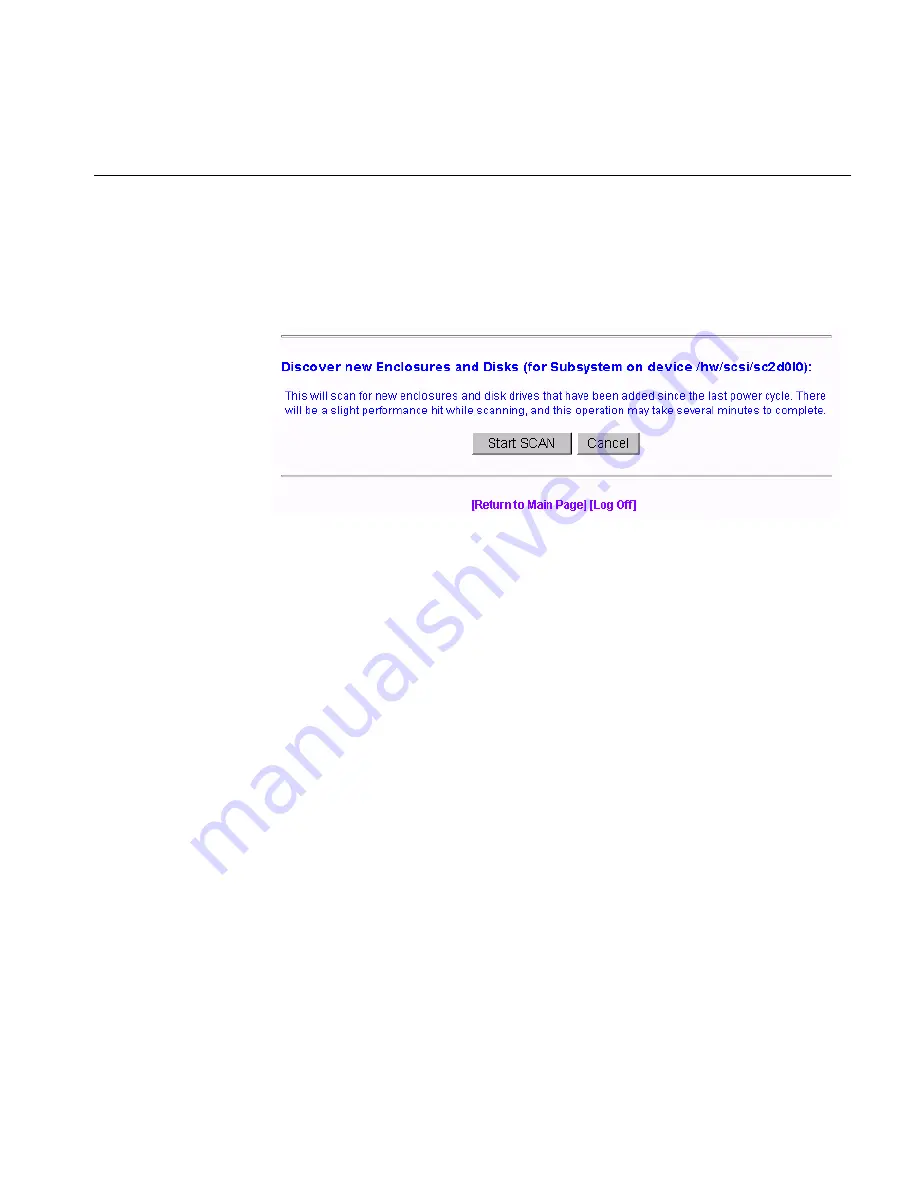
Scan for New Enclosures and Disks
When the
Scan for New Enclosures and Disks
menu selection is made (7.75 firmware),
the dialog box shown in Figure 3-110 appears.
Figure 3-110
View Controller’s Internal Event Log (7.75 Firmware)
This feature allows users to add one or more disk enclosures to a configured system
while the system continues to operate. After the enclosure or enclosures have been added
to the system, clicking
Start SCAN
on the screen shown in Figure 3-110 starts the SES
monitoring process for the new enclosure. The user can then configure the additional
disk capacity without restarting the system.
Additional enclosures are added to the configured system using the following
procedure.
1.
Check for ID conflicts. Each enclosure and disk drive must have a unique ID.
2. Resolve any ID conflicts.
3. Connect drive channels from the existing system to the new enclosure or enclosures.
4. Supply power to the new enclosure or enclosures. This causes a Loop Initialization
Primitive (LIP) on the drive channel to notify the controller that new disk drives
have been added to the fibre loop.
5. Wait for the controller to supply power to the disk drives. All disk drives must have
completed the spin-up process before proceeding.
6. Issue the scan for additional enclosures. This may be an option incorporated in the
configuration utility, or issued as a direct SCSI command.
Summary of Contents for TP9100
Page 1: ...TPM Installation Instructions and User s Guide for TP9100 007 4382 002 ...
Page 4: ......
Page 8: ......
Page 14: ......
Page 60: ...44 007 4382 002 3 Using TPM Figure 3 10 All Drive Packs Created 7 01 and Later Firmware ...
Page 65: ...Configuration Functions 007 4382 002 49 Figure 3 15 All LUNs Defined 6 14 Firmware ...
Page 87: ...Configuration Functions 007 4382 002 71 Figure 3 40 Initialization Progress 6 14 Firmware ...
Page 164: ......
Page 176: ......
Page 182: ......


