Operating manual - English
REKORD AY
Copyright Silca 2019
7
3
MACHINE DESCRIPTION
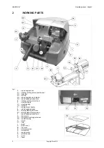
REKORD AY is a professional key-cutting machine for ABLOY keys. The machine comprises the
following main parts:
Main switch
The key-cutting machine is connected to a power supply socket provided with a differential switch.
Pressing the switch (O) powers the machine and illuminates the warning light (H1) to indicate that
current is on.
ATTENTION: switch (O) is electromagnetic, in the event of a power failure it goes out automatically. When
electricity is restored it must be reset manually to power the machine again.
Motor on switch
The motor on switch (N) is placed on the left-hand side of the REKORD AY key-cutting machine.
ATTENTION: the illuminated switch remains on to indicate that the key-cutting machine has been started
(cutter in motion).
Motor and transmission unit
The motor has belt transmission. The transmission unit is placed on the left of the motor and activates
the brush (J) and cutting tool (H1). These components are protected by two covers:
-
protective belt cover (J1),
-
top cover (M).
Mobile unit
The mobile unit comprises a carriage (C) which holds a code space setting device and a clamp for
securing the keys, with a code device for adjusting inclination (fig. 4, page 6).
The carriage (C) is fitted to the translation shaft and is moved manually by the operator.
It has been designed to avoid the accumulation of cutting dust or chippings.
The key-cutting machine has an inclined table which allows the chippings to collect in the special tray
(C1) placed under the carriage and easily removable for thorough cleaning.
W
ORKING
PARTS
The working parts are described below:
•
Brush
The brush (J) is used to eliminate burrs from the cuts and is made of non-abrasive material.
•
Cutting tool
The cutting tool (H) is the part of the REKORD AY used for cutting key blanks. The cutting tool is in HSS
super rapid steel and is protected by a special cover (M) to ensure safe operation.
•
Tracer point
The tracer point (G) housed on the left-hand side of the machine base. A centesimal ring (G2) ensures
regulation of the depth
.
•
Coded angle device
The device comprises:
-
a clamp (A1), connected directly to the inclination setting device, which acts as a key centring device
and tip stop.
-
a jaw (A2) with which to secure the key, activated by knob (B).
•
Coded spacing device
The code device comprises a knob (F) to activate a graduated slide which determines the position of
the various cuts.


