REKORD AY
Operating manual - English
14
Copyright Silca 2019
Depth setting
Depth setting is regulation of the cutting depth (fig. 12 - B).
Usually depth setting is not necessary during normal use of the machine. However, if the tracer point is
replaced or an optional carriage is used it is advisable to check the depth settings.
Regulating depth setting
To regulate the depth settings, proceed as follows
:
ATTENTION: disconnect the machine from the mains.
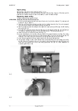
1) set up the coded spacing device by means of the knob (F) so that the indicator "5" is aligned with
position "2" (fig. 13, page 13).
2) insert the tip of the gauging calliper (provided) into the rotating clamp (A1) (fig. 14), push up against
the tip stop (A3) and lock in the calliper by turning the knob (B).
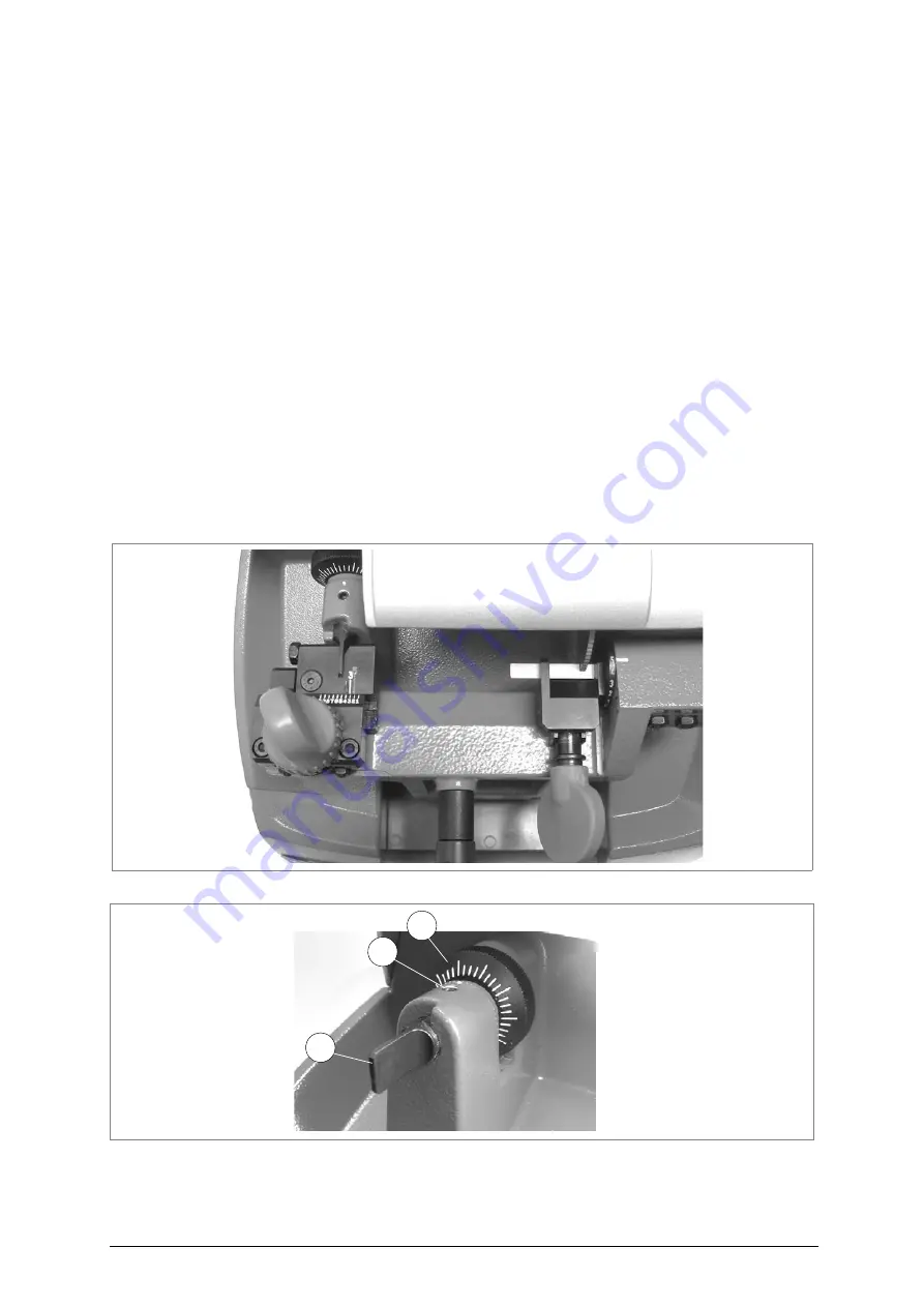
3) take the carriage towards the cutting tool and place the tracer point (G) all the way into the locating
groove (E3) (fig. 15).
4) check that the cutting tool enters clearly into the groove in the gauging calliper (fig. 15). If adjustment
is necessary, adjust axial gauging in the way described above ("Axial gauging regulation").
5) loosen the screw (G1) locking the tracer point (fig. 16).
6) use the lateral brush (J) to turn the cutting tool shaft in the opposite direction to cutting. The cutting
tool should skim the bottom of the groove on the gauging calliper. If not, turn the ring nut (G2) (fig. 16)
clockwise to move the cutting tool unit forward, or in the opposite direction to move it back.
7) when the ideal regulation has been reached, tighten the tracer point locking screw.
8) if an optional carriage is used, check that the tracer point enters freely into the locating groove (E3)
and that there is not excessive play on it. If necessary, adjust play between the locating groove and
tracer point by loosening the nut (Q) and turning grub screw (Q1) (fig. 13). When adjustment is
complete, tighten the nut (Q).
Fig. 15
Fig. 16
G2
G1
G

