30/238
Building Technologies
Modular Heating Controller RMH760B
CE1P3133en
HVAC Products
3 Commissioning
05.02.2007
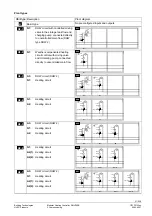
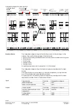
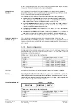
Configuration diagram for plant type H4-5
a a a a
d d
a
Q Q
x x
1
2
x
x
3
4
0...
10
V
Y
Q
d d
B
d
B
V
Q
2)
1)
3P
R1
Q
R2
Q
d
d d
Q
Y Q
a a a a
d d
a
Q
0.
..1
0 V
Y
Q
d d
B
d
B
V
Q
2)
1)
3P
a
R1
Q
R2
Q
d d
Q
a a a a
d d
a
Q
0...
10
V
Y
Q
d d
B
d
B
V
Q
2)
1)
3P
a
R1
Q
R2
Q
d d
Q
RMH760
N.X5
x
N.X6
x
N.X4
x
N.X3
x
N.X2
x
N.X1
x
A7.X3
x
A7.X4
x
A7.X2
x
A7.X1
x
RMZ789 (2)
A9.X6
x
A9.X5
x
A9.X3
x
A9.X4
x
A9.X2
x
A9.X1
x
RMZ789 (1)
( )
A2.X3
x
A2.X2
x
A2.X1
x
A2.X3
x
A2.X2
x
A2.X1
x
A3.X3
x
A3.X4
x
A3.X2
x
A3.X1
x
RMZ782 (2)
RMZ783
RMZ787
A9.X6
x
A9.X5
x
A9.X3
x
A9.X4
x
A9.X2
x
A9.X1
x
a d d d
Q
d d
B
d
B
V
Q
1)
D
C
0.
..1
0
V
a
0.
..1
0 V
Y
a
2)
3P
a d d d
Q
d d
B
d
B
V
Q
1)
D
C
0..
.10
V
a
0.
..1
0 V
Y
a
2)
3P
i
i
i
i
1
2
3
4
1. 2.
d
a
d
a
d
d
d
Q Q
Q
d
Q
d
B
d
B
V
Q
a
0...
10
V
Y
0.
..1
0 V
Y
2)
2)
1)
3P
3P
Y
d d d
a
x
x x x
a
Q
a
a d
0.
..1
0 V
Y
2)
3P
N.Y1
Y
N.Q4
Q
N.Q1
Q
N.Q2
Q
N.Q3
Q
N.Q5
Q
A9.Q2
Q
A9.Q3
Q
A9.Q4
Q
A9.Q1
Q
A7.Q1
Q
A7.Q2
Q
A7.Q3
Q
Q
A7.Q5
N1
N2
N1
N2
N3
N4
N.Y2
Y
A9.Y1
Y
A9.Y2
Y
A9.Q2
Q
A9.Q3
Q
A9.Q4
Q
A9.Q1
Q
N1
N2
N3
N4
A9.Y1
Y
A9.Y2
Y
3P
3 P
3 P
3P
3P
A2.Q2
Q
A2.Q3
Q
N1
N2
A2.Y1
Y
3P
A2.Q2
Q
A2.Q3
Q
N1
N2
A2.Y1
Y
3P
A3.Q2
Q
A3.Q3
Q
A3.Q5
Q
N1
N2
A3.Y1
Y
3P
A3.Q4
Q
3 P
31
33W
01_B
as
ic
RMZ782 (1)
V
a a
a d
a
a
d d
d
Q
Y
3P
Q Q
Y
3P
Q Q
V
d d
B
d
0.
..1
0 V
2)
B
0.
..10
V
2)
1)
B
1)
B
V
d
d d
B
d
a
Q Q
B
0.
..10
V
Y
2)
3P
Q
d
d
1)
a
A2.Q1
Q
A2.Q1
Q
A3.Q1
Q
.
Fl
ow
Re
tu
rn
R
oom
R
oom
rel
.
Ti
m
er
R
oom abs.
O
pe
rat
in
g m
od
e
cl
ose
op
en
Re
la
y 1
Re
la
y 2
Heating circuit 1
HC-
pump
Fa
ul
t bu
tton
H
eat
ing l
imi
t
He
at
in
g
Heat demand
O
per
at
in
g m
od
e
Ou
ts
id
e
Fl
ow
Re
tu
rn
R
oom
R
oom
rel
.
R
oom abs.
O
per
ati
ng m
ode
Ti
m
er
op
en
cl
ose
HC-
pump
H
eat
in
g l
im
it
O
per
at
in
g m
od
e
Flo
w
Re
tu
rn
R
oom
R
oom r
el
.
R
oom
abs
.
Ou
ts
id
e
O
per
ati
ng m
ode
Ti
m
er
cl
ose
op
en
H
ea
tin
g li
m
it
O
per
at
in
g m
od
e
HC-
pump
Heating circuit 3
Heating circuit 2
X = Universal input
Y = Analog output
Q = Relay output
x = Analog or digital
a = Analog
d = Digital
i = Pulse
=
= Contin. output
= Fault
= Feedback
= Time switch
= Holiday
= Special day
= 2-Pos. output
To do a configuration
From capital letter to capital letter
From small letter to small letter
Capital letter = Physical in- or output
Small letter = internal signal
= Or-selection
= And-selection
Heat requis.
Fr
os
t
Fl
ow
Re
tu
rn
cl
ose
op
en
Main
pump
Di
sp
la
y 1
Di
sp
la
y 2
Di
sp
la
y
3
Di
sp
la
y 4
Wi
nd
So
la
r
Ou
tsi
de
Le
gi
one
lla
fu
nc
tio
n r
ela
y
Primary
Fl
ow
Re
tu
rn
Fl
ow
Secondary
Con-
sumer
Circu-
lation
Tank
O
per
at
in
g m
od
e
cl
ose
op
en
cl
os
e
op
en
cl
os
e
op
en
Maintain.
temp.
Fl
ue
g
as
R
el
ea
se
F
lue
g
as
m
ode
.
Bu
rn
er
Bo
ile
r
Re
tu
rn
Bu
rn
er
Shuto
ff v
al
ve
Boilerp.
Bypassp.
(W
ater
s
hor
tag
e)
1
(O
ve
rp
re
ss
ure
) 2
(U
nder
pr
es
sur
e)
3
Pump funct:
Boiler
Modulating
Stage
cl
ose
op
en
Se
tp
oi
nt
c
om
p.
cl
ose
op
en
MBRT
Flo
w
Re
tu
rn
H
eat
ing
Fro
st
Primary controller
Heat requis.
System
pump
cl
ose
op
en
to
p
bo
tto
m
Fl
ow
Fo
rc
ed
c
har
gi
ng
4 Extension modules
1) 6 Single or twin pumps
2) 6 Control outputs (DC 0...10 V or 3-positioning)
3-Positioning output in pairs Q1/Q2, Q3/Q4
Configuration Diagram
RMH760B
Maximum configuration:
Plant type
Miscellaneous
Main controller
Faults
Counter
DHW
Primary
Re
tu
rn
Fl
ow
s
ig
nal
Fl
ow
cl
ose
op
en
Secondary
= from
= to
H4-5
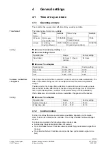
The configuration diagram shows all function blocks active in the plant type. In this
example, these are the following types of function blocks:
•
Boiler control including maintained boiler return temperature controlled via mixing valve
•
Miscellaneous
•
DHW heating
•
Heating circuit 1
•
Heating circuit 2
For additional examples, refer to subsection 16.1.4 “Examples”.
The configuration diagram shows the inputs and outputs preconfigured in the basic
module.
This means that for an input variable (e.g. the boiler temperature), an input terminal
(e.g. X1) has already been preconfigured per default.
For plant type H4-5, the following inputs and outputs are preconfigured in the boiler
temperature controller, that is, in function block “Boiler“:
Input variable
Terminal
Designation in diagram
Boiler temperature
X1
N.X1
Boiler return temperature
X3
N.X3
Output variable
Terminals
Designation in diagram
Actuator maintained boiler return
temperature
Q1 and Q2
N.Q1/Q2
1-stage burner
Q3
N.Q3
Boiler pump
Q5
N.Q5
Function blocks
Controller
Inputs
Outputs

