FEC920: USER GUIDE
Page 201
September 18
10 USER WIRING
User wiring, created from the instrument front panel, allows parameters to be wired together so that, for
example, a counter can be configured to be incremented when an alarm goes active. This can be used as an
alternative to iTools.
This section is presented as two examples that show the general techniques used to create and delete wires
from the instrument user interface.
10.1 DRIVE RELAY EXAMPLE
To drive the relay whose terminal contacts are 3A/3B, whilst the temperature being measured by Channel 2
exceeds 30°C. For this example Channel 2 alarm 1 and a hysteresis of 4°C will be used.
1.
In channel 2, Alarm 1 page (see note), set the following parameters:
Type: Abs. High
Threshold: 30
Hysteresis: 4
Latch: None
Block: Off
Dwell:00:00:00
Acknowledge: No
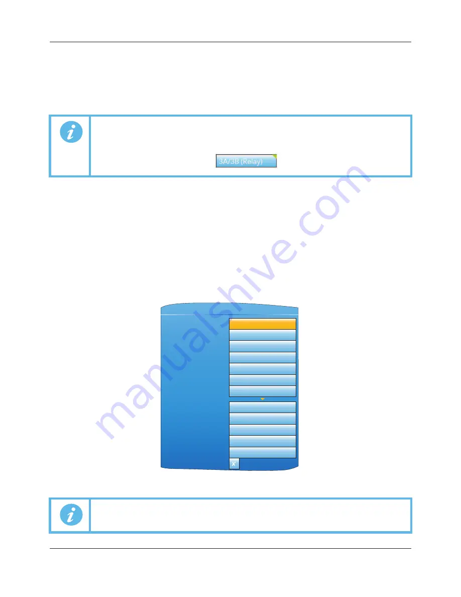
Figure 130 Channel 2, Alarm 1 set up
Note: 1. These examples refer to Channel Configuration and to Virtual Channel configuration,
descriptions of which are to be found in Section 6.4 and Section 6.5, respectively.
Note: 2. The destination parameter field has a small green triangle at the top left corner to indicate
that it has a wire routed to it.
Note:
The channel alarm areas of configuration become accessible only once the channel with
which they are associated has been configured with a suitable ‘Type’ (Section 6.4.1).
3A/3B (Relay)
Abs Hi
Active Not ackd
30.0
4.0
None
Off
00:00:00
Type
Status
Threshold
Hysteresis
Latch
Block
Dwell
Channel.2.Alarm1
No
Yes
No
Yes
No
Acknowledge
Active
Inactive
N.acknowledged
Acknowledgement
Inhibit
A5E45696052A Rev-AA


