FEC920: USER GUIDE
Page 190
September 18
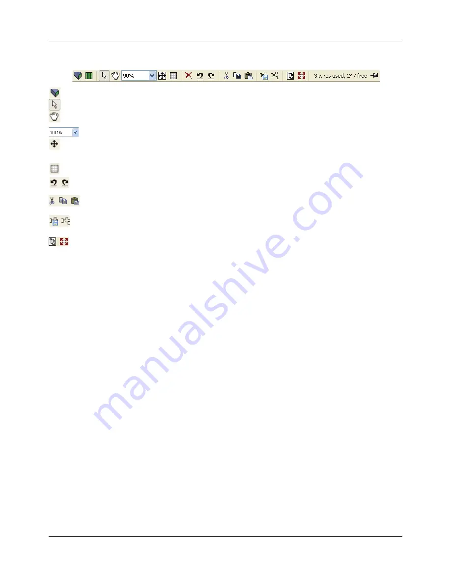
9.3.1 Tool bar
9.3.2 Wiring Editor Operating Details
COMPONENT SELECTION
Single wires are shown with boxes at ‘corners’ when selected. When more than one wire is selected, as part of
a group, the wire color changes to magenta. All other items have a dashed line drawn round them when
selected.
Clicking on a single item selects it. An Item can be added to the selection by holding down the control key (Ctrl)
whilst clicking on the item. (A selected item can be deselected in the same way.) If a block is selected, then all
its associated wires are also selected.
Alternatively, the mouse can be click-dragged on the background to create a ‘rubber band’ round the relevant
area; anything within this area being selected when the mouse is released.
<Ctrl>+<A> selects all items on the active diagram.
BLOCK EXECUTION ORDER
The order in which the blocks are executed by the instrument depends on the way in which they are wired. Each
block displays its place in its sequence in a colored block in the bottom left-hand corner (Figure 119).
FUNCTION BLOCKS
A Function Block is an algorithm which may be wired to and from other function blocks to make a control
strategy. Each function block has inputs and outputs. Any parameter may be wired from, but only parameters
that are alterable in Operator Mode may be wired to. A function block includes any parameters that are needed
to configure or operate the algorithm. The inputs and outputs which are considered to be of most use are always
shown. In most cases all of these need to be wired before the block can perform a useful task.
If a function block is not faded in the tree (left hand pane) it can be dragged onto the diagram. The block can
be dragged around the diagram using the mouse.
Download wiring to instrument.
Mouse select. Select normal mouse operation. Mutually exclusive with ‘Mouse Pan’ below.
Mouse Pan. When active, this causes the mouse cursor to change to a hand-shaped icon. Allows the
graphical wiring diagram to be click-dragged within the GWE window aperture.
Zoom. Allows the magnification factor of the wiring diagram to be selected.
Pan tool. Whilst left clicked, the cursor appears as a rectangle showing which part of the wiring diagram is
currently displayed. Click dragging allows the rectangle to be moved freely about the diagram. The size of
the rectangle depends on the zoom setting.
Show/Hide grid. This toggles an alignment grid on and off.
Undo, redo. Allows the user to undo the last action, or, once an undo action has taken place, to undo the
undo. Short cuts are <Ctrl>+<Z>. for undo; <Ctrl>+<V>, for redo.
Cut, Copy, Paste. Normal Cut (copy and delete), Copy (copy without delete) and Paste (insert into)
functions. Shortcuts are: <Ctrl> + <X> for ‘Cut’; <Ctrl> + <C> for copy and <Ctrl> + <V> for Paste.
Copy diagram fragment; Paste diagram fragment. Allows a part of the wiring diagram to be selected,
named and be saved to file. The fragment may then be pasted into any wiring diagram, including the source
diagram.
Create compound; Flatten compound. These two icons allow compounds to be created and ‘un-created’
(flattened).
A5E45696052A Rev-AA


