


63
SICK LSI Technical Description - 06/98
Forklift wheel
∅
35cm
Frictional wheel
∅
3,5cm
with incremental encoder
Distance covered by vehicle
Calculation of pulses per centimetre
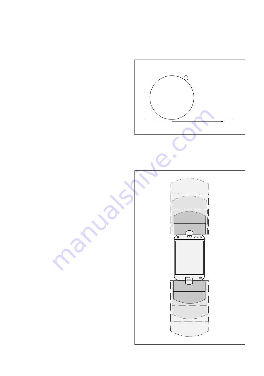
Example 3: Driverless Transport System (DTS), forward and
reverse
PF1
WF1
WF2
PF2
WF3
PF3
PF4
WF4
PF5
WF5
PF6
WF6
protective
fields for
forward
movement
protective
fields for
reverse
movement
For vehicle protection
Example 3: Driverless Transport System (DTS), forward and
reverse, with incremental encoders
Determine the number of pulses your incremental encoders
deliver per centimetre covered by your vehicle.
The result is dependent on the number of pulses the
incremental encoder delivers per revolution and on the
transmission ratio between the vehicles running wheel and the
frictional wheel on which the incremental encoder is mounted.
How to calculate the number of pulses per centimetre:
The running wheel of a forklift has a diameter of 35 cm.
The frictional wheel on which the incremental encoder is
mounted has a diameter of 3.5 cm.
The incremental encoder used delivers 1000 pulses per
revolution.
Circumference of
forklift wheel = d x
π
= 35 cm x
π
= 109.96 cm
One revolution of the forklift wheel corresponds to ten
revolutions of the frictional wheel and thus to 10,000 pulses of
the incremental encoder.
From this the number of pulses of the incremental encoder per
centimetre covered by the vehicle is calculated as:
Pulses/cm = 10,000: 109.96 = 90.94
When configuring the incremental encoder in the PLS/LSI user
software you must thus enter the rounded value 91 under
Pulses per centimetre.
The user software calculates from that figure the maximum
permissible speed of the vehicle.
(How to configure the incremental encoders in the PLS/LSI user
software is described in section 9.7).
The LSI system is configured as follows:
Two PLS sensors connected
Six monitoring areas defined (the protective and warning
fields are configured in stages, as shown in the diagram)
Two incremental encoders connected and configured
Two OSSD outputs and two warning field outputs configured
Six monitoring cases configured (three for forward, three for
reverse)
Any order of monitoring cases
(The circuit diagrams relating to this example are on the next
page.)


