


61
SICK LSI Technical Description - 06/98
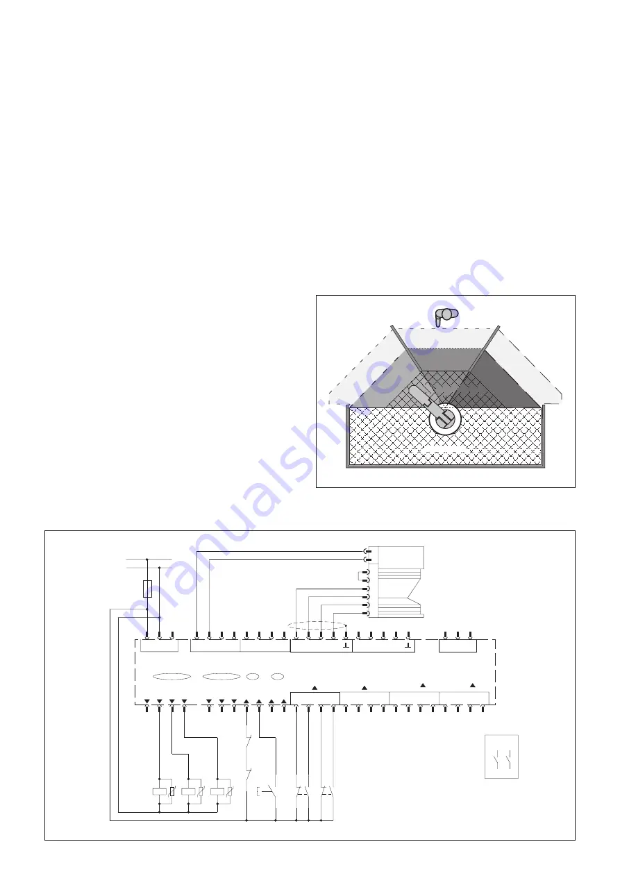
11 Appendix
PF3
PF2
PF1
WF2
WF1
WF3
hazardous area
PLS
Example 1: Machining centre with three load positions
2
3
5
6
3
1
7
COM
(D)
SPEED INPUT
7
4
2
3
D2
1
D1
3
SENSOR 2
4
1
2
3
INPUT
C1
B1
A2
B2
SENSOR 1
C2
INPUT
6
(C)
SPEED INPUT
1
-
+
-
+
B
A1
RES B
EDM B
RES A
A
EDM A
POWER OUT
+
+
-
-
B
OSSDB1
WZ B
OSSDA2
OSSDB2
POWER OUT
0 V
+24V DC
Si
-
+
-
A
OSSDA1
WZ A
ERROR
POWER IN
S1A
K2
K1
K1
K2
K6
y
1)
x
y
x
k2
k1
PLS
LSI
7
8
3
4
1
3
2
1
11.1 Application examples
Notes:
Also follow the instructions given in the technical description of
the PLS.
The application examples presented on the following pages are
intended only as an aid. You may need to incorporate additional
protective measures.
A risk exists that personnel could be inside the protection field
before it is monitored by the PLS. Ensure that fields are selected
before any hazard is likely to arise.
For area protection
Example 1: Machining centre with three load positions
The LSI system is configured as follows:
One PLS sensor connected
Three monitoring areas defined (the protective and warning
fields are shown in the diagram)
One OSSD output and one warning field output configured
Three monitoring cases configured, activated via the binary
inputs
Alternative order of monitoring cases
Note on the circuit diagram:
Use only relays with positively-driven contacts.
The protective elements switched in parallel with the contactors
are for arc suppression.
1) Output circuits. These contacts are to be incorporated into
the controller such that, when the output circuit is open, the
hazardous state is controlled.
In categories 3 and 4 to EN 954-1, they must be
incorporated on two channels (x, y paths).


