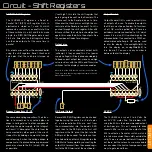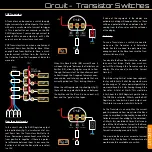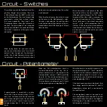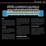
The Manual
There is quite a lot of information in this man-
ual, so here is a run down of each section and
what you are likely to find.
The manual is a work in progress and we
would appreciate your feedback. Please head
to the forums if you have any ideas or con-
structive criticism. As the manual is digital, we
will be updating it regularly.
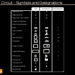
Use this table to identify the different compo-
nents, connections and features of the PCB
and schematic.
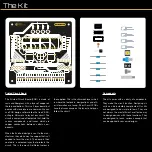
This is the PCB design, which features the
ground plane that’s on the back of the board.
This isn’t shown on the PCBs silkscreen, but
you can see it’s borders if you angle the board
at a light.
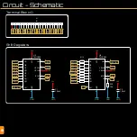
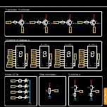
The schematic shows the circuit design in it’s
simplest form. Each part of the circuit is shown
separately. Connections within these sections
are shown with white lines. You can find tags
next to pins connected to other parts of the
circuit. Each tag has a corresponding tag in
the part of the circuit that it is connected to.
The Bill of Materials (BOM) is a list of parts and
their values. This can be used to find replace-
ment parts or to check the datasheets for each
component.
The rest of the Circuit section of this manual
explains how and why the circuit works. You
can skip this bit and head straight to building
your kit, then check back later to learn how it
works. Or you can go head first into the how
and why, then start building. It’s up to you.
This is where you can learn how to solder
your components to the PCB. The tips at the
start are very useful. They may prevent you
from getting frustrated. The soldering iron can
be hard to tame. Make sure to keep that tip
tinned and shiny! The diagrams on the right
pages show the components mentioned in
the instructions. You can use this to match the
components to the footprints on the board,
and to make sure you are using the correct
resistor in the correct place.
Be sure to go through this section to minimise
any risk of breaking something. If you have a
short and you connect the board to power, you
might overheat a component, or burn out the
power supply.
Follow the tutorial to make your D13 LED blink.
This is the famous sketch that most people
start with when programming Arduinos and
Arduino compatible boards.
Here are some of the devices you can make
when combining your Motherboard with other
kits from Short Circuits. Be sure to check out
the selection at www.shortcircuits.cc
The Component Index will give you details
about each component (except some connec-
tors). We’ve included information about how
the component works, its construction, how to
find out if it has failed and much more. You can
use this as a reference when designing circuits
or trying to fix them.


