18
Assembly Instructions
General Soldering tips
1. ALWAYS KEEP YOUR TIP CLEAN
To ensure the soldering iron can transfer
enough heat from it to your solder/compo-
nent leg you must keep the tip clean and
shiny. A dull tip means the outside layer
of metal has oxidise. This oxidised layer
is a poor transferrer of heat. Because of
this, you will have to hold the tip against
the component for a longer period of time,
which can result in the component failing.
It’s also very frustrating.
To keep your soldering iron tip clean, wipe
it on a wet sponge or wire ball, then apply
some solder to coat it, then wipe it again.
Ideally, you should do this after every com-
ponent. At the very least, do it after every
4 components.
2. CONTACT
When soldering, make sure the tip of your
iron is making contact with both the leg of
the component and the pad on the PCB.
Apply heat to the area, then, within a sec-
ond or two, apply the solder to the point
of contact.
3. HEAT
It is better to be too hot than too cold. As
mentioned earlier, when the iron tip isn’t hot
enough, you have to hold it on longer. This
allows heat to transfer into the component
and could cause a failure. It is better to set
your soldering iron a little hot so the solder
melts instantly and flows around the leg of
the component with ease. You can start at
around 350oC and adjust from there.
4. SOLDER
Leaded solder is much easier to work with,
which makes it easier to learn with. It can
be hard to find in some countries, but can
often be ordered from China. There are po-
tential health risks, but these are very low.
Make sure you have a fan pointing away
from your work area to blow the fumes
away. Work in a well ventilated area.
Thinner is better. Working with a thick wire
of solder can get messy. Use 0.4-0.5mm
solder for more control. You will have to
feed more into the solder joint, but you
have more control when there are other
pins close by that you want to avoid. This
is essential when soldering surface mount
components and Integrated Circuits.
5. SAFETY
350oC is obviously very hot. Stuff catches
fire at this temperature. Skin fries. Please
be careful. Remember to turn it off when
you are finished. This will prevent a poten-
tial house fire and also save your iron tip
from continued oxidation.
6. ANGLE OF ATTACK
When soldering, make sure you position
the board so that it is easy to access the
area you are working on. It is easy to make
a mistake when you are trying to maneuver
your iron into position around some obsta-
cle. You may have to spin the board 180
degrees, or make sure you have snipped
the legs off the previous component. It’s
easy to be impatient so try to plan ahead.
Resistors
Bend each leg of the resistor by 90 de-
grees, as close to the resistor as possible
(fig.1). The holes are fairly close together,
so this step is important. Then insert the
legs into the correct holes by finding the
correct reference (R1, R2 etc) on the board,
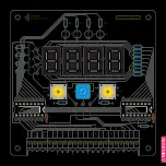
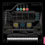
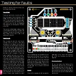
or by using the picture on the next page as
a guide. Polarity is not important with resis-
tors, so either way is fine.
Hold the resistor in place with sticky tack
or tape, then flip the board over, ready for
soldering. Solder each leg by holding the
soldering iron tip to the leg and the pad,
then apply the solder to the joint. Let it flow
around the leg and create a shiny cone. Use
flush cutters to cut the legs off, then briefly
hold the soldering iron to the joint to re-flow
the solder.
Ceramic Capacitors
Install the ceramic capacitors into the cor-
responding holes (C1, C2). They will easily
fall out, so add some sticky tack or tape to
secure them. Polarity does not matter. Flip
the board and solder the pins to the pads,
then trim and re-flow.
104
104
C1, C2
100nF (0.1uF)
R1-4
R5-6
R7-14
R15
R16
R17
R18
R19
1.2K
10K
560Ω
2K
10K
1.5K
1.2K
10K
fig.1


