14
Circuit - Transistor Switches
Circuit - 7-Segment Displays
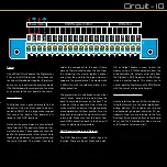
The Matrix
To avoid using a Shift Register for each
digit, the segment displays are wired up in
a matrix. This means that cathodes with the
same letter from each of the displays are
connected together. For example, segment
A from U1, U2, U3, and U4 are all connected
to one output of the second Shift Register
(U6) through a current limiting resistor.
The downside to a matrix, is that you need to
cycle through the digits one at a time in or-
der to show a different number on each digit.
U2
U1
U3
U4
R7-14
560
Ω
SEG-G
SEG-F
SEG-A
SEG-B
SEG-DP
SEG-C
SEG-D
SEG-E
DIGIT_1
DIGIT_2
DIGIT_3
DIGIT_4
This makes the code more complicated, and
the results in a dimmer display. However,
freeing up IO pins on the microcontroller to
interface with other devices is a much bet-
ter payoff.
LEDs in Parallel
Because of the matrix the segment LEDs are
wired in parallel. If all 4 digits were on at the
same time, the distribution of voltage across
the 4 LEDs could be unbalanced and cause
dimming in some of the segments. Fortu-
nately, this is avoided when cycling digits
.
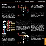
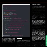
Current Limiting Resistors
To calculate the current limiting resistor’s
value, we will need to consider the voltage
drop (CE) across the Transistor. This can be
found by looking at the CE Voltage drop vs.
Collector Current graph in the transistor’s
datasheet. The segments are bright enough
at 5mA and only one digit will be on at a time,
so we can use 5mA as our current.
R = V
source
- V
LED
- V
CEsat
R = 5 - 2 - 0.1
I 0.005
R = 580Ω
(560Ω nearest common value)
With these values we can calculate the value
of our Base Resistors (R1-4).
First we calculate the current needed at the
Base.
I
B
= IC I
B
= -0.04 I
B
= -0.004A
H
FE
10
Then we use Ohm’s law to calculate the Re-
sistance needed.
R = V R = -5 R = 1250Ω
I -0.004
So we now know that a 1200Ω resistor would
result in the Transistor operating in saturation
mode, allowing enough current at the Collec-
tor for our display, with minimal resistance.
To ensure we turn the Transistor on fully we
can use a lower Current Gain for our calcu-
lation. There are different methods to ensure
your calculations result in hard saturation. We
will use the h
FE
of 10 method, which is com-
monly used.
So we know the Collector Current to be
around -40mA and we will assume the Current
Gain to be 10. We also know that Vcc is 5V.


