CIRCUIT
Circuit - IO
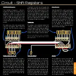
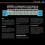
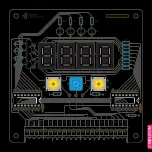
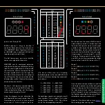
Power
Like all Short Circuit boards, the Digitiser has
2 Vcc and 2 GND terminals. This allows you
to chain multiple boards together. Simply use
one set as an input from the previous board
(The Motherboard for example) and the other
as an output to the next board in the chain.
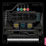
Ground Plane
The Digitiser uses a ground plane to link all
the parts of the circuit that need to be con-
nected to GND. This is a large area of copper
that covers the back of the board and is
linked to the 2 GND terminals.
Note how the ground plane is connected to
these terminals. The pads are linked via ther-
mal relief spokes. These spokes connect the
pad to the ground plane in four places while
leaving a gap between the ground plane and
the rest of the pad. This makes it easier to
solder the component to the pad. If there
were no thermal relief spokes, the heat from
the soldering iron would rapidly conduct
away from the pad into the large amount of
copper in the ground plane. This would make
it difficult to melt the solder and form a reli-
able connection.
The ground plane is only broken when other
circuit traces need to be routed along the
back to avoid other traces on the front. This
is done as little as possible. Care is taken to
make sure that no parts of the ground plane
are completely cut off from another. Also, it is
important to consider the electrical current’s
return path. Make sure that the paths from
each GND connection back to the Power IO
are as unobstructed as possible.
Shift Register Inputs and Outputs
The Shift Registers need 3 data inputs to
function. These are Serial, Clock and Latch.
OE or Output Enable is used to dim the
display using a PWM enabled pin from the
microcontroller. Qh’ outputs serial data from
the Digitiser’s Shift Registers to Shift Reg-
isters on another board. This allows you to
control both the Digitiser and the RGB Matrix
with the same 3 microcontroller pins.
Human Interface Devices
Human Interface Devices (HIDs) include any-
thing that humans use to control digital com-
puting devices. This includes your mouse
and keyboard, gamepad, and other PC pe-
ripherals. Here, we are referring to the two
Switches (think mouse buttons or keyboard
keys), and the Potentiometer (like a mouse
scroll wheel or volume control).
J1
SW
2
POT
SW
1
SW
2
POT
SW
1
LAT
CLK
SER
OE
LAT
CLK
SER
Qh’
LAT
CLK
SER
Qh’
GND
VCC
VCC
GND
Shift Register In/Out
Power In/Out
HIDs Out


