COMPONENTS
Shift Register - 74HC595
Overview
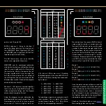
The 595 Shift Register is an 8-bit serial-in,
parallel-out shift register. This means it
takes 8 bits, one bit at a time as in input and
shift those out at the same time as outputs.
They are referred to as SIPO (Serial In, Par-
allel Out), rather than PISO, SISO, or PIPO.
Shift Registers are used to store data. They
store data using flip flops / latches, which
have two stable states, either on or off,
which is of course represented by a logic
level 1 or a 0. Flip flops are made from lots
of transistors.
SIPO shift registers are great for reducing
the number of microcontroller pins needed
to control lots of outputs. A PISO shift reg-
ister would be used to read multiple inputs
on just a few microcontroller pins.
Physical Construction
Troubleshooting
Important Ratings
Quick Reference
The best way to troubleshoot an IC is to
swap it out and see if the circuit works
with a known working IC. If the circuit still
doesn’t work, then the fault is in a different
component. If it does start working with the
new IC, then the problem is fixed.
Check the pinout diagram and check each
pin. The GND pin should obviously read 0V
with a multimeter. The Vcc pin should read
the same as your circuits voltage source.
You would need an oscilloscope to read the
serial, clock, serial out and latch pins, as
these change voltage from 0 to Vcc many
times a second. If the output pins are read-
ing well below Vcc when turned on, they
are probably supplying too much current.
Reduce the load on the output.
If you don’t have a spare IC to replace the
potentially broken one, try desoldering the
IC, or removing it from its socket. You can
then build a simple circuit to test its func-
tionality on a breadboard. Hook it up to a
microcontroller programmed to send all 1’s
to the shift register, then test each output’s
voltage in respect to GND. If they all read
around Vcc then they are OK. Now set the
outputs to all 0’s. Test them again. They
should now all read 0V. If nothing chang-
es, then there may be something wrong
with the input lines, or the code. If they all
change accept one, then there might be
something wrong with the output. Either
way, you will need to replace the IC.
How do these things break? Well, they will
most likely break from using it outside of its
recommended ratings. This could be from
asking for too much current from a single
output, or the total current from all outputs.
It could also be from applying more voltage
than the specifications allow.
integrated circuit die
(not from 74HC595)
bonding wire
terminal pins
plastic casing
index marking
Always check the max ratings and calcu-
late the amount of current going through
each output, and the total across the whole
IC and compare these numbers with the
datasheet.
If your circuit is asking too much of the shift
register, look for one with more max cur-
rent. There are many flavours of shift reg-
ister to choose from. You could always use
transistor switches to reduce the current
draw, or lower the current for each output
with a higher value current limiting resistor.
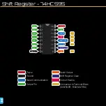
74HC595
15
1
2
3
4
5
6
7
9
14
11
10
12
13
QA
QB
QC
QD
QE
QF
QG
QH
QH’
SER
SRCLK
SRCLR
RCLK
OE
VCC
GND
8
16
Check
Polarity
Positions
16
Type
Schematic
Symbol
PCB Symbol
Designator
IC
U
Parameter
Min. Typ. Max.
Operating temperature
Supply Voltage (V
CC
)
-0.5
Input Clamp Current
Output Clamp Current
Continuous Output Current (Output)
Continuous Current (Vcc or GND)
High Level Input Voltage (4.5V Vcc)
Low Level Input Voltage (4.5V Vcc)
5V
3.15V
150°C
7V
±20mA
±20mA
±35mA
±70mA
1.35V

