Resistor
Overview
Resistors do exactly that, they resist the
flow of electrons through them. This resis-
tance, measured in Ohms (Ω), is fixed and
can be relied on to compliment integrated
circuits, divide voltages and protect other
components from too much current. But
due to the law of conservation of energy,
this energy needs to go somewhere. In this
case, it is converted into heat. This is why it
is important to take note of the power rating
of resistors, measured in Watts (W).
Resistors can be made out of many mate-
rials, but most commonly metal or carbon
film. the film is wrapped around a ceramic
core and the whole thing is protected by
an insulated layer, usually cream, or blue
in colour.
Physical Construction
Quick Reference
Common Varieties
Important Ratings
Troubleshooting
If a resistor is bad you can usually tell. It
likely went up in a puff of grey smoke. as
soon as you exceed the resistors power
rating, it’s going to get hot. Fortunately they
are cheap and easy to replace. and easy
to troubleshoot. Keep in mind that resis-
tance cannot be measured in an operating
circuit. Voltage and Current can however.
So you could use Ohms law to calculate
the resistance.
1. Remove one lead from the circuit
2. Turn your multimeter to its resis-
tance setting
3. Set your multimeter to the lowest
range that exceeds the value of
the resistor
4. Place the multimeter’s probes
on each of the resistors leads
(polarity doesn’t matter) and note
the reading.
5. If the value is outside the range of
tolerance, then the resistor is bad
and needs replacing.
insulated casing ceramic core
ceramic core
connector
metal/carbon film
Check
Polarity
Positions
2
Type
Schematic
Symbol
PCB Symbol
Designator
passive
R
Parameter
Typical Values
Resistance (
R
)
0
Ω - 10GΩ
Power Rating (
W
)
0.1W - 250W
Tolerance (
%
)
±0.01% - ±10%
Temp Coefficient (
ppm/°C
)
±15 - 50ppm/°C
Max Voltage (
V
)
200V - 500V
Min Operating Temp (
°C
) -70 - -25
°C
Max Operating Temp (
°C
) 70 - 450
°C
Through
Hole
Surface
Mount
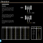
01C
COMPONENTS

