ASSEMBL
Y
Power up the Motherboard via USB or with
a 5V power adapter wired to its Power in
Terminals. The PWR LED should light up on
the Motherboard. If not, check the Mother-
board’s manual for tips.
Upload the code in the following chapter
and check if all the LEDs and segments
are lit.
If none of them are lit, check power is get-
ting to the board. Set your multimeter to DC
Voltage: ( ). Put your red multimeter lead
on VCC and the black lead on GND. The
multimeter should read somewhere between
4.6V and 5V. If not, check the your VCC
and GND connections. Recheck for shorts.
Check polarities again. Check everything
that should be connected is, and everything
that shouldn’t isn’t.
Segments or LEDs not working
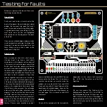
If a whole digit is not working, check the
transistor it is connected to for solder bridg-
es and follow the circuit back to the shift
registers output pin.
If the same segment on each of the digits is
not working, then check the resistor and the
shift register output pin it is connected to.
If an LED isn’t working, check its connection
with its shift register output and try swap-
ping LEDs to check the LED and the circuit
at the same time.
If the potentiometer or the switches don’t
work, it is probably something to do with the
code. Check for a bridge near the terminal
blocks, then check your code.
Still having problems? Head over to the
forums on our website for help and sup-
port. www.shortcircuits.cc
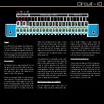
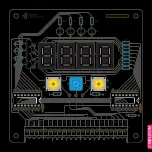
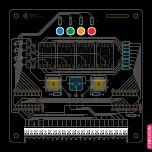
Q1-4
U2
U1
U3
U4
SW1
R1-4
R5
RV1
R6
R7-14
SW2
U5
D1
C1
J1
R15
R16
R17
R18
D2
D3
D4
74HC595
U6
74HC595
C2
R19
SW
2
POT
SW
1
SW
2
POT
SW
1
LAT
CLK
SER
OE
LAT
CLK
SER
Qh’
LAT
CLK
SER
Qh’
GND
VCC
VCC
GND
BACK

