COMPONENTS
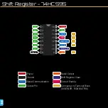
Shift Register - 74HC595
Controlling the Shift Register
The 595 shift register can hold 8 bits of
data, which are received through its Serial
data line. When the Clock pin pulses, the
current value of the Serial pin is shifted into
the register. For the shift register to accept
data, the Latch pin must be Low. Here is
a diagram of the process of shifting 8 bits
into the register.
ShiftOut
To achieve this shifting of bits in an Arduino
sketch, we use the function ShiftOut(). This
is already built in to the Arduino IDE, so you
don’t have to write it in your sketch. You
can just call the function. For reference,
the code it uses is something like the code
opposite.
A for loop runs 8 times (once for each bit).
It checks whether you are using LSBFIRST
or MSBFIRST, then sets the Serial pin to the
first bit of the byte depending on the order.
It then sets the clock pin high then low to
shift the bit in.
Clock
Serial
Latch
1
0
0
0
0
1
1
1
A
B
C
D
E
F
G
H
1
0
1
0
1
1
0
0
74HC595
void
shiftOut
(
uint8_t
dataPin,
uint8_t
clockPin,
uint8_t
bitOrder,
uint8_t
val)
{
uint8_t
i;
for
(i = 0; i < 8; i++)
{
if
(bitOrder == LSBFIRST)
digitalWrite
(dataPin, !!(val & (1 << i)));
else
digitalWrite
(dataPin, !!(val & (1 << (7 - i))));
digitalWrite
(clockPin,
HIGH
);
digitalWrite
(clockPin,
LOW
);
}
}


