24
have a short between Vcc and GND. You can
jump over to the Power Test. If you here a
constant sound from your meter when the
probes are in contact with Vout and GND
then you have a short. Check the back of the
board again for solder bridges. Focus on the
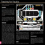
areas marked with boxes on the diagram on
the next page. This is where Vcc and GND
are closest.
Polarity
Check all the components that are polarity
Testing for faults
Before you power on the board, there are a
few things we need to do.
Visual Check
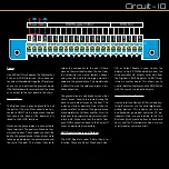
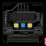
Firstly we need to do a visual check of the
back of the board. We are looking for solder
bridges that connect two pads that aren’t
meant to be connected. A magnifying glass
is a good tool to have when doing this. The
most likely areas for this are highlighted
with red boxes on the diagram of the back
of the PCB.
If you see any solder bridges, bring your iron
up to temperature and drag it between the
two pads. You may have to repeat this a few
times. Make sure your iron is clean or the
solder won’t cling to it.
Short Circuits
Now we need to check for short circuits
(the bad kind). If we have a short circuit
somewhere on the board and we connect
it to power, we could damage something.
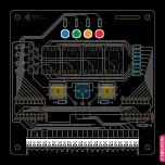
So to check for shorts, get your multimeter
and put it in continuity mode ( ) Make sure
the black cable is plugged into the common
socket and the red cable into the red socket
that also has the Ω symbol on it. Touch the
probes together and make sure it makes a
sound. Now press the black probe on one
of the green circles indicated in the diagram.
These are all connected to the large ground
plane on the underside of the board. Keep
it held there while you press the red probe
onto one of the red circles indicated in the
diagram. The screw of the Vout terminal and
the GND terminal (the metal screw is con-
nected to ground) are the most convenient.
Making sure they are both making contact
with metal, listen for a sound from your mul-
timeter. If there is none, excellent, you don’t
dependent. In this circuit, that would be
the LED’s, the Transistors and the Shift
Registers.
Powering the Board
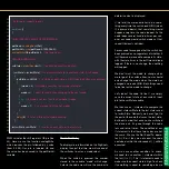
We can now connect the Digitiser to the
Motherboard. Connect VCC, and GND to
the Motherboards Power Out terminals, and
SER, CLK and LAT to any of the digital IO
terminals (make note to change the code to
reflect which pins you have connected the
data lines to).
J1
Q1-4
U2
U1
U3
U4
SW1
R1-4
R5
RV1
R6
R7-14
SW2
U5
D1
C1
R15
R16
R17
R18
D2
D3
D4
74HC595
U6
74HC595
C2
R19
S
W
2
PO
T
S
W
1
S
W
2
PO
T
S
W
1
L
A
T
CL
K
SE
R
O
E
L
A
T
CL
K
SE
R
Qh
’
L
A
T
CL
K
SE
R
Qh
’
GND
VCC
VCC
GND
DIGITISER


