Capacitor - Ceramic
COMPONENTS
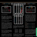
Another form of filter that uses capacitors
is an RC filter. The most common RC fil-
ters are low-pass and high pass filters.
As the name suggests, the low-pass filter
lets low frequency signals pass but not
high frequencies. High pass filters simply
achieve the opposite. This is a passive
filter as it uses passive components (resis-
tors and capacitors). The following are the
simplest of low-pass and high-pass filters,
the equation that governs their properties
and a graph to show the typical relation-
ship between frequency (Hz) and amplitude
(given in volts).
Time Delay
In an RC circuit, capacitors take time to
reach their maximum store of electrical
energy when exposed to a voltage source,
and to deplete that store when the voltage
source is removed. This can be used to
create a time delay between turning on a
voltage supply and a component receiving
the voltage it needs to turn on, or read a
logic level high for on a microcontroller for
example. We can use a simple equation to
work out how much time it will take the ca-
pacitor to reach approximately 63% of the
supply voltage. This is referred to as the RC
time constant and uses the symbol tau (T).
In the example circuit the LED will gradual-
ly get brighter until the capacitor reaches
capacity, following the curve of the graph.
Low-Pass Filter
High-Pass Filter
Time Delay Circuit
C
R
Input
Output
+
-
+
-
f
cutoff
f
cutoff
=
1
2
πRC
Volts
Frequency
f
cutoff
=
1
2
πRC
C
R
Input
Output
+
-
+
-
Volts
Frequency
f
cutoff
C
1000uF
R
10k
Input
+
-
T
(seconds)
= R(Ohms) x C(farads)
T
= 10,000 x 0.001
T
= 10 seconds
Volts
Time Constant
(
T
)
LED
1
T
2
T
3
T
4
T
5
T

