26
Coding Basics - Dimming and Switches
The following code example and explana-
tion will test all of the Digitiser’s functions
and teach you the basics. We will cover the
following:
• Using the potentiometer to bright-
en and dim the display
• Using a switch to make changes
to the display
• Addressing shift register outputs
to change what is displayed
1
2
3
4
5
6
7
8
9
10
11
12
13
14
15
16
17
18
19
20
21
22
23
24
25
26
27
28
29
30
31
32
//Output Pin Variables
const int
SER = 3;
// Shift Register Serial Data pin
const int
CLK = 4;
// Shift Register Clock pin
const int
LAT = 5;
// Shift Register Latch pin
const int
OE = 10;
// Shift Register Output Enable pin
//Input Pin Variables
const int
sw1 = A0;
// Switch 1 pin
const int
Pot = A1;
// Potentiometer pin (must be analog pin)
const int
sw2 = A2;
// Switch 2 pin
//Other Variables
int
mode = 1;
// counter for Mode select
int
swState = 0;
// Holds the current state of the switch
int
lastswState = 0;
// Holds the previous state of the switch
int
potRead = 0;
// Holds the current potentiometer value (0-1024)
int
potDimVal = 0;
// Holds the converted dimming value for output to OE (0-255)
//Void Setup - runs once at start
void
setup
()
{
pinMode
(OE,
OUTPUT
);
pinMode
(SER,
OUTPUT
);
pinMode
(CLK,
OUTPUT
);
pinMode
(LAT,
OUTPUT
);
analogWrite
(OE, 0);
}
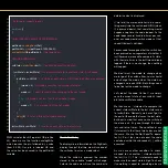
The usual setup is required. This includes
adding variables for pins, adding variables
for other functions, assigning pins as out-
puts etc. Copy the code (with or without
comments) to your sketch or download the
full sketch
.
The pin variables tell the microprocessor
which pins to address when the code ex-
ecutes. The other variables will handle the
numbers we need to make everything work.
If you need clarification on this section of the
code, please refer to the Coding Basics sec-
tion of the Motherboard’s Manual. To help
you understand the code,
comments
have
been added. When the Arduino IDE compiles
the code ready to transfer it to the micro-
controller, it ignores everything after // on a
single line and between /* and */ for multiple
line comments.
Potentiometer Dimmer
At the beginning of our loop we will set our
dimming value using the potentiometer. We
first store the current value read at the pin
our Potentiometer is connected to. We store
this value as potRead (
line 41
). We then need
to convert this value to something we can
send to our OE pin. Analog pins return a val-
ue between 0 and 1023. Our PWM pins use
a value from 0 to 255. To “map” these values
we use the
map
function (
line 42
).
map
(value,fromLow,fromHigh,toLow,toHigh)
The
map
function expects 5 values between
its brackets. The first, value, is the input
value you are mapping. In this case, the
reading from the potentiometer, potRead.
We then need to set the range of this val-
ue. As the analog pin returns a value from
0-1023 we will use 0 as the low value and
1023 as the high value.
The function then expects the range that this
will be mapped to. This will be the PWM val-
ues between 0 and 255. As you can see, we
have used these in reverse. This is because
the OE pin of the shift register is active low.
So 0V or 0 will be fully on, and 5V or 255
will be fully off.
Now that potDimVal is equal to the mapped
value of potRead, we can use this to set our


