background image

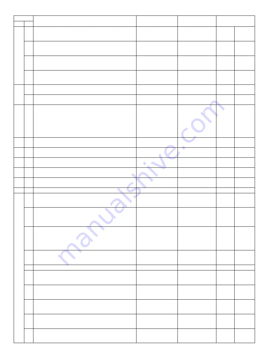
AR-M350 SIMULATIONS 10-2

8

1

Used to check and adjust the developing bias voltage in each 
print mode and its control circuit. 

Adjustment, 
operation test, check

Process (OPC drum, 
developing, transfer, 
cleaning)

2

Used to check and adjust the main charger grid voltage in each 
print mode and its control circuit. 

Adjustment, 
operation test, check

Process (OPC drum, 
developing, transfer, 
cleaning)

6

Used to check and adjust the transfer charger current and its 
control circuit. 

Adjustment, 
operation test, check

Process (OPC drum, 
developing, transfer, 
cleaning)

17

Used to set and check the transfer roller output. 

Operation test, check

Process (OPC drum, 
developing, transfer, 
cleaning)

Operation

9

1

Used to check the operation under load (clutches and 
solenoids) in the duplex section and their control circuits. 

Operation test, check

Duplex

Operation

2

Used to check the sensors and detectors in the duplex section 
and their control circuits. 

Operation test, check

Duplex

Operation

10

0

Used to check the operation of the toner motor and its control 
circuit. 
(Note) 
Do not execute this simulation with toner in the toner hopper. 
If executed, toner will enter the developing section, causing an 
overtoner trouble. Be sure to remove toner motor from the toner 
hopper before execution. 

Operation test, check

Process (OPC drum, 
developing, transfer, 
cleaning)

Operation

13

0

Used to cancel the self diag "U1" trouble. 
(Only when FAX is installed.)

Cancel 
(incase of a trouble)

Trouble

14

0

Used to cancel the self diag "U1/LCC/US/PF" troubles. 

Cancel 
(incase of a trouble)

Trouble

Error

15

0

Used to cancel the self diag "U6 (09/20/21/22)" trouble. 

Cancel 
(incase of a trouble)

Paper feed

Trouble

16

0

Used to cancel the self diag "U2" trouble. 

Cancel 
(incase of a trouble)

Trouble

Error

17

0

Used to cancel the self diag "PF" trouble 
(when copy is inhibited by the host computer).

Cancel 
(incase of a trouble)

Communication 
(RIC/MODEM)

Trouble

Error

21

1

Used to set the maintenance cycle. 

Setup

Spec

Counter

22

1

Used to check the print count in each section and in each 
operation mode. (Used to check the maintenance timing.)

Adjustment, setup, 
operation data output, 
check (display, print)

Counter

2

Used to check the number of total misfeed and troubles. 
(If the number of misfeed is considerably great, the machine 
must be repaired. The misfeed rate is obtained by dividing this 
count by the total counter value.)

Adjustment, setup, 
operation data output, 
check (display)

Trouble

3

Used to check the misfeed position and the number of misfeed 
at that position. 
(If the number of misfeed is considerably great, the machine 
must be repaired.) 
(Sections other than DSPF sections)

Adjustment, setup, 
operation data output, 
check (display)

Trouble

Misfeed

4

Used to check the total trouble (self diag) history.

Adjustment, setup, 
operation data output, 
check (display)

Trouble

5

Used to check the ROM version of each unit (section).

Other

Software

6

Used to print the list of adjustments and setup data 
(simulations, FAX soft switches, counters). 

Adjustment, setup, 
operation data output, 
check (print)

Data

Setup, 
adjustment 
data

7

Used to display the key operator code. 
(Used when the customer has forgotten the key operator code.)

Adjustment, setup, 
operation data output, 
check (display)

Data

User data

8

Used to check the number of use of the staple, DSPF, and 
scanner (reading) unit. 

Adjustment, setup, 
operation data output, 
check (display)

Counter

9

Used to check the number of use (print quantity) of each paper 
feed section.

Adjustment, setup, 
operation data output, 
check (display)

Paper feed

Counter

10

Used to check the system configuration 
(option, internal hardware). 

Adjustment, setup, 
operation data output, 
check (display)

Spec

Option

Code

Function (Content)

Purpose

Section

Item

Main Sub

  '     !"#$%&

Summary of Contents for AR-M350 Imager

Page 1: ...e safety and performance of the set SHARP CORPORATION LASER PRINTER AR M350 MODEL AR M450 OPTIONS AR EF1 AR M11 AR RK1 CODE 00ZARM350 A1E 1 PRODUCT OUTLINE 1 1 2 CONFIGURATION 2 1 3 SPECIFICATIONS 3 1 4 CONSUMABLE PARTS 4 1 5 EXTERNAL VIEWS AND INTERNAL STRUCTURES 5 1 6 UNPACKING AND INSTALLATION 6 1 7 DISASSEMBLY AND ASSEMBLY MAINTENANCE 7 1 8 MACHINE OPERATION 8 1 9 ADJUSTMENTS 9 1 10 SIMULATION...

Page 2: ......

Page 3: ...ILYLLE ÄLÄ KATSO SÄTEESEEN CLASS 1 LASER PRODUCT LASER KLASSE 1 For Europe CLASS 1 LASER PRODUCT LASER KLASSE 1 LUOKAN 1 LASERLAITE KLASS 1 LASERAPPARAT CAUTION INVISIBLE LASER RADIATION WHEN OPEN INTERLOCKS DEFEATED AVOID EXPOSURE TO BEAM VORSICHT UNSICHTBARE LASERSTRAHLUNG WENN ABDECKUNG GEÖFFNET UND SICHERHEITSVERRIEGELUNG ÜBERBRÜCKT NICHT DEM STRAHL AUSSETZEN ADVARSEL USYNLIG LASERSTRÅLNING VE...

Page 4: ...cedure 6 2 5 AR EF1 AR RK1 6 6 6 Automatic developer adjustment 6 8 7 Adjustment of distortion 6 8 8 AR M11 6 9 7 DISASSEMBLY AND ASSEMBLY MAINTENANCE 1 Self print of set values 7 1 2 Maintenance System Table 7 1 3 Disassembly and assembly 7 4 8 MACHINE OPERATION 1 Acceptable originals 8 1 2 Standard original setting orientation 8 1 3 Automatic copy image rotation rotation copying 8 1 4 Adjustment...

Page 5: ...rinter AR P350 P450 When installing the AR EF1 to the above laser printer the printer controller must be replaced with this multi function controller C Scanner rack AR RK1 This rack is required when installing the scanner unit AR EF1 with duplex DSPF to the laser printer AR P350 P450 M350 M450 To install this rack the machine must be equipped with the large capacity paper feed desk AR D13 or the 3...

Page 6: ...er stand AR D14 Printer model 45ppm AR P450 MFP model 35ppm AR M350 B W Scanner module DSPF AR EF1 Standard Scanner Rack AR RK1 Standard Stand MPD 2000 sheet paper drawer AR D13 or Three paper drawer stand AR D14 Power supply unit AR DC1 MFP model 45ppm AR M450 B W scanner module DSPF AR EF1 Upper exit tray extension AR TE4 Finisher AR FN6 Mail bin stacker AR MS1 Stand MPD 2000 sheet paper drawer ...

Page 7: ...e Power supply unit Duplex module bypass tray Duplex module Multi purpose drawer Stand 3 x 500 sheet paper drawer Stand MPD 2000 sheet Duplex module bypass tray Duplex module Upper exit tray extension Multi function controller board Fax memory 8 MB B W scanner module DSPF Saddle stitch finisher Finisher Mail bin stacker Exit tray Punch unit PS3 expansion kit Facsimile expansion kit Print server ca...

Page 8: ...ed toner disposal Toner recycling system Resolution Write 600dpi Smoothing Write 1200dpi equivalent Gradation Write 2 levels C C E E B D A Paper size Printable area Paper size A B C D E A3 297 420 4 289 4 B4 257 364 4 242 4 A4 210 297 4 202 4 B5 182 257 4 168 4 A5 148 210 4 140 4 Japanese postcard 100 148 4 92 4 Ledger 279 432 4 271 4 Legal 216 356 4 208 4 Foolscap 216 330 4 208 4 Letter 216 279 4...

Page 9: ...e machine Macintosh 680x0 Power Macintosh iMac G3Macintosh Custom PS Windows 95 98 Me Windows NT 4 0 Windows 2000 Mac OS 7 6 to Mac OS 9 Custom PCL5e 6 XL SPDL Windows 95 98 Me Windows NT 4 0 Windows 2000 PPD Windows 95 98 Me Windows NT 4 0 Windows 2000 Mac OS 8 5 1 Mac OS 9 PCL6 compatible PCL5e compatible PostScript Level 2 compatible PostScript 3 compatible When an optional PS3 expansion kit is...

Page 10: ...ible with HP LaserJet 4000 Small margin difference rendering difference by different font family default and transfer function difference are not to be included in the compatibility All the PJL commands are not necessarily included in the compatibility PCL6 compatibility Target for PCL6 is to be compatible with HP LaserJet 4000 Small margin difference rendering difference by different font family ...

Page 11: ... 300 items in conjunction with those of FAX Sequential broadcasting O E mail only It is not available for FTP Desktop Simultaneous FAX transmission O Specifying multiple destinations of FAX E mail or FTP and broadcasting by a single scan Transmitting functions Rotating transmission O to be matched with FAX specification Long length original transmission X Verification stamp function Option Report ...

Page 12: ...stems is detected and the settings will accordingly be changed Reading resolution dpi Copy mode Magnification 25 99 100 101 200 201 400 OC 600x600 600x600 600x600 600x600 OC High speed 600x600 600x300 600x600 600x600 DSPF SPF standard 600x300 600x300 600x600 DSPF SPF high quality 600x600 600x600 600x600 Input and transmitting resolution dpi FAX transmit mode Selection mode Standard Fine Super fine...

Page 13: ...on Original size detection Provided Sizes to be detected Automatic one detection unit to be used with software modification by destination Inch 1 Default at overseas 100V base engine 11 x17 8 5 x14 8 5 x11 8 5 x11 R 5 5 x8 5 Inch 2 11 x17 8 5 x13 8 5 x11 8 5 x11 R 5 5 x8 5 AB 1 Default at Japan domestic 100V overseas 200V base engines A3 B4 A4 A4R B5 B5R A5 A3 B4 A4 A4R A5 8 5 x11 216x330 mm AB 2 ...

Page 14: ...x1 x1 x1 x1 100K AR 450KA1 6 Upper heat roller kit Upper heat roller Fusing separation pawl Upper x1 x4 200K AR 450UH 7 Lower heat roller kit Lower heat roller Fusing separation pawl Lower x1 x2 200K AR 450LH 8 Cleaner blade Cleaner blade x10 50K x10 AR 450CB AR 450CB AR 450BL x10 9 Cleaning roller Cleaning roller Bearing x10 x20 200K x10 AR 450CR AR 450CR AR 450RC x10 10 Staple cartridge Staple c...

Page 15: ... x1 x1 x1 x1 x1 100K AR 450KA 6 200K PM kit Upper heat roller Lower heat roller Fusing separation pawl Upper Fusing separation pawl Lower Cleaning roller Bearing x1 x1 x4 x2 x1 x2 200K AR 450KB 7 Staple cartridge Staple cartridge x3 3000x3 AR SC1 Common with cartridge for AR FN4 AR FN6 8 Staple cartridge Staple cartridge x3 5000x3 AR SC2 Common with cartridge for AR FN7 NO Name Content Life Produc...

Page 16: ... x1 x1 x1 100K AR 450KA 6 200K PM kit Upper heat roller Lower heat roller Fusing separation pawl Upper Fusing separation pawl Lower Cleaning roller Bearing x1 x1 x4 x2 x1 x2 200K AR 450KB 7 Staple cartridge Staple cartridge x3 3000x3 AR SC1 Common with cartridge for AR FN4 AR FN6 8 Staple cartridge Staple cartridge x3 5000x3 AR SC2 Common with cartridge for AR FN7 NO Name Content Life Product name...

Page 17: ...AR 450KA 6 200K PM kit Upper heat roller Lower heat roller Fusing separation pawl Upper Fusing separation pawl Lower Cleaning roller Bearing x1 x1 x4 x2 x1 x2 200K AR 450KB 7 Staple cartridge Staple cartridge x3 3000x3 AR SC1 Common with cartridge for AR FN4 AR FN6 8 Staple cartridge Staple cartridge x3 5000x3 AR SC2 Common with cartridge for AR FN7 NO Name Content Life Product name Remark 1 Toner...

Page 18: ... 8 9 Number Indicates the day of the month of packing 10 Letter Indicates the production factory A for Nara Plant 1 2 3 4 5 6 7 1 Version number A sequentially revised 2 Numeral figure Indicates the end digit of the production year 3 Letter Indicates the production factory B for SOCC 4 Destination code 5 6 Numeral figures Indicates the production day 7 Numeral figure or X Y Z Indicates the product...

Page 19: ...nal guides Adjust to the size of the originals 4 Document feeder tray Set the originals here for automatic feeding 5 Operation panel Use for operation of copier network scanner and facsimile features and for printer configuration operations 6 Document cover 7 Document scanning windows Sheet type originals are scanned here 8 Document glass All originals which cannot be copied from the document feed...

Page 20: ...ing is being performed 5 COPY key Press to select the copy mode and display the basic screen of the copy mode Even when the machine is busy in another mode the basic copy mode screen will appear when the COPY key is pressed If this key is pressed and held while the basic screen of the copy mode is displayed the total output count and the quantity of toner remaining percentage will be displayed 6 J...

Page 21: ...6 SPECIAL MODES key Touch to display the special modes selection screen 7 Paper size display The display shows the location of the paper trays the size of the paper in the trays and the approximate amount of paper loaded in each tray The approximate amount of paper in a tray is indicated by 8 Original size display The original paper size will be displayed when originals are placed on the document ...

Page 22: ... used the list of stored print jobs is displayed here up to 100 jobs The job retention function can be used only if the printer is equipped with a hard disk drive unit If the main switch is turned off stored print data will be cleared 4 Display scroll keys Use these keys to view the job hold list when it is contained on more than one screen 5 CONDITION SETTINGS key Use to switch the display to the...

Page 23: ...e relevant job key to select the job and execute the desired operation using the keys described in 7 8 and 9 2 Mode switching key Use to switch the job list between JOB QUEUE and COMPLETE JOB QUEUE Displays the list of the current job and the reserved jobs COMPLETE Displays the list of completed jobs 3 PRINT JOB key Use to display the print job list for all modes print copy network scan and fax 4 ...

Page 24: ...nsor 2 SLD2 15 No 2 mirror 8 CCD lens unit 16 Original exit roller Code Name Active condition 1 SPSD SPF original resist front sensor 2 SCOV SPF paper feed cover sensor 3 SDD SPF original set sensor 4 SOCD OC open close sensor 5 Original size sensor PWB Light emitting side 6 SLD1 SPF original length sensor 1 7 SLD2 SPF original length sensor 8 SPF original width detection volume PWB 9 Original siz...

Page 25: ... disassembled Image scan SPF back surface 10 CIS interface PWB in CIS unit The CIS unit cannot be disassembled CIS signal AD conversion process 11 Scanner interface PWB Scanner unit and connection of scanner control PWB 12 CIS control PWB CIS unit control and image process 13 CL inverter PWB Inverter for copy lamp 14 Scanner control PWB Scanner unit control No Name Function Operation 1 SPFM SPF mo...

Page 26: ...DU4 AR DU3 AR DU4 AR MS1 AR DC1 AR FN6 AR DC1 AR FN7 AR PN1A B C D No Yes Duplex bypass device installed No No No Finishing device installed Scanner document feeder installed Yes Yes Yes Controller board facsimile unit or other electric devices installed When installing a paper feeding device an optional power supply unit or a duplex bypass device be sure to reattach the rear cabinet the AC inlet ...

Page 27: ...the paper feed option units AR D13 or AR D14 should have been installed A Removal of the machine 1 Remove the cushioning materials from the right and left of the front side 2 Remove the locking tape from the right and left sidesof the tray Then Remove the top of the carton and lower the plastic bag covering the machine while the machine is still on the carton base 3 Remove the packing tape from th...

Page 28: ... the desk frame 2 Pull out the upper paper tray of the stand paper drawer until it stops and attach the front mounting plates using a supplied screw for each Then remove the lock of the paper tray and close the tray Remove the locks of the middle tray and the lower tray similarly 3 Reattach the paper tray of the main unit 3 Remove the rear cabinet of the stand paper drawer and remove the AC inlet ...

Page 29: ...f the stand paper drawer to the power supply unit Connect the relay harness of the stand paper drawer to the connector of the power supply unit 7 Attach the rear cabinet of the stand paper drawer 1 Pass the cord of the power supply unit through the hole of the rear cabinet and attach the rear cabinet to the stand paper drawer 2 Attach the AC inlet cover to the rear cabinet of the stand paper drawe...

Page 30: ...eloper cartridge evenly B Note Before opening the developer seal shake it 4 or 5 times 5 Attach the top cover to the developer cartridge and install the cartridge to the machine D Toner cartridge settings 1 Remove a new toner cartridge from the package and shake it horizontally five or six times 2 Insert a new toner cartridge Push the cartridge in until it locks securely into place 3 Gently remove...

Page 31: ...nsert two racks A securely all the way into two racks B respectively as shown in the illustration and use four screws M4 x 8 respectively to secure the racks in the order of 1 to 2 in the illustration 2 Cut the rear cabinet of the desk unit Cut the cut off portions on both ends of the rear cabinet of the desk unit by hand and remove them Parts included for the rack Screws M4 x 8 8 pcs Screws M3 x ...

Page 32: ...r unit put the scanner unit on the rack from the front of the rack by positioning the unit to the rack as shown in the illustration and gently slide the unit until it stops at the end of the rack 6 Secure the scanner unit Secure the scanner unit that has been put on the rack to the rack with three M4 stepped screws 7 Remove the securing tape and securing screw for packing Remove all pieces of pack...

Page 33: ...on Since adjustment was made at the shipment any additional adjustment is not needed basically If distortion occurs as shown in the illustration however perform the adjustment by following the procedure below 1 Use a level meter to check that the scanner unit is installed on a horizontal surface Make a copy If distortion occurs as shown in Fig 1 or Fig 2 loosen the cam A securing screw M3 x 12 to ...

Page 34: ...emove the print server card the HDD PWB the expansion memory the PS Kanji font ROM and the E2PROM from the removed printer control PWB unit and mount them to the positions of the MFP control PWB unit shown in the illustration Installation of print server card 1 Remove the screws that fix the cover and remove the cover 2 Insert the connector of the print server card to the connector of the MFP cont...

Page 35: ...e main switch located on the front side of the main unit to the ON position 8 Check the operation 1 Check to see if the indicators on the operation panel of the scanner module are lit and key operation is available 2 Place an original in the scanner module and check to see if copying can be performed normally 3 For setting change of the printer drivers on the computer see the supplied operation ma...

Page 36: ... replace or adjust as necessary Clean Replace Adjust Lubricate Move position Unit name Part name When calling 50K 100K 150K 200K 250K 300K 350K 400K Remark Optical section Mirror Lens Reflector Sensors Table glass OC White reference glass Rails Drive belt Drive wire Pulley DSPF Paper feed section Take up roller Note 2 Separation pad Note 2 Paper feed roller Note 2 Transport section PS roller Expos...

Page 37: ...g F R Transfer roller collar After transfer star ring TR gear Screen grid Drum separation pawl UN Charger case M C Charging plate saw teeth Developing section Developer Supplied when installing DV blade DSD collar DV side seal F DV side seal R Toner cartridge Attached when installing EX Japan 814g user replacement for every 27K Fusing section Upper heat roller Lower heat roller Upper separation pa...

Page 38: ... Multi purpose Paper feed separation section Paper feed rollers Note 3 Torque limiter Note 3 Transport section Transport roller Transport paper guides Drive section Gears Specified position Belts Other Sensors Finisher Transport section Transport rollers De curler roller Transport paper guides Drive section Gears Specified position Belts Other Sensors Discharge brush Staple un Replace UN at 100K s...

Page 39: ...3 Disconnect the grounding wire 3 S Slide the SPF unit to the bottom then remove it 2 Scanner section a Rear cabinet rear lower cabinet 1 Remove the scanner rear cabinet and the rear lower cabinet b Left cabinet 1 Remove the original exit tray and remove the scanner left cabinet c Right cabinet 1 Remove the scanner right cabinet 1 1 2 3 3 4 5 5 5 6 7 1 2 3 4 2 1 1 2 3 3 4 1 2 1 1 2 1 2 1 ...

Page 40: ...emove the rear cabinet 4 Remove the scanner upper cabinet unit f Original detection PWB Light emitting side 1 Remove the rear cabinet 2 Remove the original detection unit Light emitting side 3 Remove the original detection PWB Light emitting side g Scan motor removal 1 Remove the scanner rear cabinet and the rear lower cabinet 2 Pull out the harness from the scanner control PWB 3 Remove the scan m...

Page 41: ...r j Scanner control PWB 1 Remove the scanner rear lower cabinet 2 Disconnect the connector and earth band and pull out the scanner control PWB When the scanner control PWB is replaced the EEPROM must be replaced k Operation panel unit 1 Remove the operation panel lower cabinet 2 Remove the harnesses 3 Remove the scanner right cabinet 4 Remove the operation panel unit 2 3 1 1 2 3 1 1 2 2 5 3 4 1 2 ...

Page 42: ...B Light receiving side 1 Remove the operation panel lower cabinet 2 Remove the original detection PWB light receiving side o Scan lamp 1 Remove the table glass 2 Remove the scan lamp unit p CCD lens unit 1 Remove the table glass 2 Remove the dark box cover 3 Remove the CCD lens unit Note The CCD lens unit is factory adjusted before shipping Since these adjustments cannot be performed in the market...

Page 43: ...ion 1 scale of the scribed line corresponds to 0 3 of magnification ratio If this adjustment is not satisfactory make a fine adjustment with SIM 48 1 Refer to the adjustment described below q Scanner interface PWB 1 Remove the table glass 2 Remove the PWB cover and the harness cover 3 Remove the scanner interface PWB 3 D SPF unit a Upper transport unit 1 Remove the upper transport unit cover 2 Rem...

Page 44: ...s d D SPF control PWB 1 Remove the SPF PWB and remove the D SPF control PWB e Original length sensor 1 Remove the OC cover 2 Remove the original length sensor cover and remove the sensor f Original width detection volume 1 Remove the OC cover 2 Remove the original length sensor cover 3 Remove the volume cover and remove the volume 1 1 2 1 2 3 4 3 4 3 4 1 2 3 3 3 4 5 4 4 1 1 2 3 4 3 1 1 2 3 3 4 4 1...

Page 45: ...to the paper size mark on the tray Refer to the SIM 53 6 or 53 7 g Original paper feed unit 1 Remove the OC cover 2 Remove the SPF lower cover 3 Remove the original paper feed unit h Take up roller paper feed roller 1 Remove the upper transport unit cover 2 Remove the paper feed roller cover 3 Remove the hook of each roller and remove each roller i CIS unit 1 Remove the upper transport unit cover ...

Page 46: ...d before shipping Since these adjustments cannot be performed in the market never touch the following screws of the CIS unit j Open sensor 1 Remove the open sensor k Paper exit sensor 1 Remove the paper exit sensor l Paper exit roller 1 Remove the original paper feed unit 2 Remove the paper exit roller gear 3 Remove the paper exit frame and remove the paper exit roller 1 2 2 2 2 3 1 1 1 a a a 1 2 ...

Page 47: ... SPF resist roller unit 2 Remove the SPF resist roller and the SPF resist roller clutch o SPF paper feed unit original paper feed solenoid SPF original paper feed clutch 1 Remove the SPF paper feed unit 2 Remove the SPF paper guide 3 Remove the SPF pickup unit 4 Remove the original paper feed solenoid and the SPF original paper feed clutch 1 1 2 2 3 4 1 1 1 2 3 3 2 3 4 1 1 2 3 4 5 1 6 1 1 2 1 1 1 ...

Page 48: ...riginals with two or three holes place them so that the punched edge is at a position other than the feed slot 2 Standard original setting orientation Descriptions of functions that follow in this manual assume that originals are oriented as shown Place originals in the document feeder tray or on the document glass so that the top of the original is positioned to the rear side of the machine If no...

Page 49: ...feed counter Toner concentration temperature correction low temperature side cancel temperature Final toner concentration sensor output value Desk 2 LCC 2 paper feed counter Toner concentration temperature correction high temperature side correction quantity Toner cartridge IC chip destination Manual paper feed counter Toner concentration temperature correction high temperature side judgment tempe...

Page 50: ... FAX SOFT SW etc Trouble history Printer counter Jam history FAX reception counter Destination setup FAX transmission counter Language setup Trouble counter Toner save mode setup Jam counter 13 setup Auditor setup Serial number Middle binding mode AMS setup PC Modem communication trouble detection YES NO setup Tag number setup γ change value Exposure mode setup OC SPF exposure correction value Pri...

Page 51: ...inisher installed Paper size B4 3 0mm 0 0mm 3 0mm 0 1mm unit Paper size A4R 3 0mm 0 0mm 3 0mm 0 1mm unit Paper size Ledger 3 0mm 0 0mm 3 0mm 0 1mm unit Paper size Letter R 3 0mm 0 0mm 3 0mm 0 1mm unit Print key operator program list Key operator code change Set code 00000 System settings Default settings Print density level Normal DAKER DARKEST LIGHTEST LIGHTER Disable notice page printing Yes No ...

Page 52: ...Original size detection photo sensor check H Original size detection photo sensor adjustment I D SPF hinge height adjustment J D SPF hinge diagonal adjustment Front K Scan magnification ratio adjustment L OC scan lead edge adjustment M Original off center adjustment N Image density adjustment O DSPF width detection adjustment Default Set range Measurement pin High voltage probe impedance Monitor o...

Page 53: ...ixing screws of the LSU unit 8 Print the grid pattern again and check it 9 Repeat procedures 7 to 10 until the printout is in the specified range 10 After completion of the work apply screw lock to the screws Specifications B Print off center adjustment This adjustment is performed in the following cases When the center is misaligned in printing When the LSU is replaced When the option paper feed ...

Page 54: ...e glass and check it At that time set the test chart correctly If it is set in a distorted position the adjustment cannot be made correctly 3 If the output value is not in the specified range perform the following adjustment 4 Adjust the distortion In the case of Fig 1 Shift cam A in the direction A by the difference in the copy image For one scale one groove shift by 0 5mm After shifting tighten ...

Page 55: ... Insert the front rear mirror base drive wire into the frame groove and press and fix it with the wire holder At that time do not tighten the wire fixing screw Change the direction of the lamp positioning plate F and R 2 Push the copy lamp unit onto the positioning plate and tighten the wire fixing screw Note for assembling the copy lamp unit After fixing manually shift the copy lamp unit a few ti...

Page 56: ...ection light emitting unit gently and select 1 and press START key without placing an original 3 Check that COMPLETE is displayed on the LCD and press CUSTOM SETTING key and the screen returns to the original menu 4 Place an A3 or WLT original on the table glass and select 2 and press START key When COMPLETE is displayed on the LCD the adjustment has been completed 5 After completion of adjustment...

Page 57: ...ation ratio adjustment 1 Place a print of self print pattern A3 or WLT 70 or a scale on the table glass 2 Close the original cover and make a copy 3 Check that the value is within the specification 4 If not adjust with SIM 48 1 5 Make a copy again and check again that the value is within the specification Specification Specification Adjustment Document size detection photo sensor adjustment COMPLE...

Page 58: ...Change the value with 10 key and perform the copy adjustment The rear void adjustment is changed by the step of 0 1mm When the rear edge void is too small increase the value When the rear edge void is too great decrease the value 9 Press CA key to cancel the simulation Specification Specifications Adjustment position Adjustment value SPF sub scan direction magnification ratio 0 5 SIM 48 1 Set valu...

Page 59: ...ng the simulation There are two methods the collective adjustment and the individual adjustment of the copy quality mode Copy mode FAX mode a b Specification 1 5mm Print lead edge Adjustment position Measurement reference Specification Set value Default Range Print off center SIM 50 10 Tray 1 Tray 1 Output pattern center line As shone in the table below 50 0 99 Set value 1 0 1mm shift Tray 2 Tray ...

Page 60: ...1 9 0 KODAK GRAY SCALE 1 2 3 4 19 A SHARP CORPORATION MADE IN JAPAN UKOG 0162FCZZ 1 10 W 2 3 4 5 6 7 8 9 Quality mode Linked simulation data AE3 0 AE CH3 0 Character sim46 9 MIX3 0 Character Photo sim46 10 PH3 0 Photo sim46 11 Mode EXP Chart No Adjustment level Chart No Adjustment level Character 3 3 Copied 2 Not copied Character Photo 3 3 Copied 2 Not copied Photo 3 3 Copied 2 Not copied Auto 3 C...

Page 61: ... 11 AND PRESS START 0 TRAY SELECT 1 COPY START 2 EXP LEVEL 3 1 0 4 1 5 5 2 0 6 2 5 7 3 0 8 3 5 9 4 0 10 4 5 11 5 0 1 SIMULATION 46 9 EXP LEVEL SETUP CHAR 2 INPUT VALUE 0 99 AND PRESS START 3 1 0 50 SIMULATION 46 9 EXP LEVEL SETUP CHAR 2 SELECT 1 5 AND PRESS START FEED TRAY 1 TRAY1 2 TRAY2 3 TRAY3 4 TRAY4 5 MFT 1 SIMULATION 46 9 EXP LEVEL SETUP CHAR 2 NOW COPYING SIMULATION 46 9 EXP LEVEL SETUP CHA...

Page 62: ...finisher paper width direction The adjustment is made by changing the alignment plate home position in the paper width direction by software Adjustment Finisher Operation 10 Used to adjust the console finisher AR FN7 Adjustment Finisher Operation 20 Used to check the mail bin stacker AR MS1 sensor Operation test check Mail bin stacker Operation 21 Used to check the operations of the mail bin stack...

Page 63: ...7 0 Used to cancel the self diag PF trouble when copy is inhibited by the host computer Cancel incase of a trouble Communication RIC MODEM Trouble Error 21 1 Used to set the maintenance cycle Setup Spec Counter 22 1 Used to check the print count in each section and in each operation mode Used to check the maintenance timing Adjustment setup operation data output check display print Counter 2 Used ...

Page 64: ...aintenance this counter must be cleared Only when FAX is installed Data clear FAX Counter 11 Used to reset the drum rotation time toner motor rotation time and developer rotation time counters The developer counter of the DV unit installed is reset Data clear Process OPC drum developing transfer cleaning Counter Developer DV unit 15 Used to clear each counter in the scanner mode Data clear Counter...

Page 65: ...display Operation test check Paper feed Operation 2 Used to adjust the detection level of the manual paper feed tray paper width detector Adjustment Paper feed Operation 7 Used to enter the adjustment value of the manual paper feed tray width detection level Adjustment setup Paper feed Operation 11 Used to check the width detection level of the multi purpose tray paper width detector Operation tes...

Page 66: ...uality 17 Used to adjust the CCD CIS shading reference value Setup check Picture quality 18 Used to adjust gamma density gradient in each copy mode Adjustment Picture quality Density 19 Used to adjust gamma density gradient in the auto copy mode and to set the density detection area and to set the image process mode Adjustment Picture quality Density 20 Used to adjust the copy density correction i...

Page 67: ...memory Operation test check Image process ICU Operation 61 1 Used to check the operations of the LSU unit Operation test check Operation 2 Used to adjust laser power absolute value in the copy mode Adjustment Operation 3 Used to adjust laser power absolute value in the FAX reception mode Only when FAX is installed Adjustment Operation 4 Used to adjust laser power absolute value in the printer mode...

Page 68: ...X sound signals Sound output IC operation check Send level 0dB Max Only when FAX is installed Operation test check Fax Operation 9 Used to check the output operation of the FAX sound signals Sound output IC operation check Only when FAX is installed Operation test check Fax Operation 10 Used to clear all data of image memory memory send receive Confidential data are also cleared Only when FAX is i...

Page 69: ...to download the FAX program Only when FAX is installed Inhibited Fax 24 Used clear the FAST memory data Only when FAX is installed Inhibited Fax 25 Used to register the FAX number for MODEM dial in Only when FAX is installed Inhibited Fax 26 Used to register the external telephone number for MODEM dial in Only when FAX is installed Inhibited Fax 27 Used to register the voice warp transfer number O...

Page 70: ...ose Operation test check Function Content Used to check the operations of the automatic document feeder unit and its control circuit Section DSPF Item Operation Operation Procedure Select with 10 digit key pad 1 High speed operation 2 Low speed operation 2 2 Purpose Operation test check Function Content Used to check the operations of the sensors and detectors in the automatic document feeder unit...

Page 71: ... Jogger RHP FSS Staplesensor JFHP Jogger F HP FSTHPS Stapler HP sensor SCID2 Staplecompiler paper entry detection 2 FSHPS SlideHPsensor STTHP2 Staplerotation HP detection2 FLE Liftlock sensor STTHP1 Staplerotation HP detection1 FLLLS Liftlower limitsensor STUHP Stapleshift HP detection FULS Liftupper limit sensor PSHP Pusher HP detection FFE Bookbinding clock sensor PPD Paper holdreturn detection ...

Page 72: ...e jogger stop position in the finisher paper width direction The adjustment is made by changing the alignment plate home position in the paper width direction by software Section Finisher Item Operation Operation Procedure Enter the adjustment value with 10 digit key pad and press START key The jogger moves to LT position Inch series or A4 position AB series according to the entered value and stop...

Page 73: ...section desk paper feed large capacity trays and their control circuits Section Paper feed Item Operation Operation Procedure The display is highlighted when detected 3 tray desk LCC DDRS Desk door sensor TDRS Tandem side door sensor DSPD2 Desk cassette 2 remaining paper quantity sensor TTSD Tandem tray sensor DSPD1 Desk cassette 1 remaining paper quantity sensor TLUD2 Tandem tray 2 upper limit se...

Page 74: ...h 7 MCPCL LCC multi paper feed clutch 8 DMM Desk transport motor 8 TMM LCC transport motor 3 tray desk LCC SIMULATION 4 3 DESK LCC LOAD TEST SELECT 1 AND PRESS START 1 2 2 SIMULATION 4 3 DESK LCC LOAD TEST EXECUTING 1 2 2 Press START key to get started Press CUSTOM SETTING key to stop Main code 5 5 1 Purpose Operation test check Function Content Used to check the operations of the lamps and LCD on...

Page 75: ... DCPR DC power relay 4 MM Main motor 5 DM Drum motor 6 DSB_FW Stepping motor forward rotation 7 DSB_RV Stepping motor reverse rotation 8 CPFC Paper feed clutch 9 RRC Resist roller clutch 10 TRC Transport roller clutch 11 FGS_FIN Finisher gate solenoid 12 LUM Tray 1 lift up motor 13 TRC_DSK Desk clutch sync signal 14 PSPS Separation pawl solenoid 15 1 MCM MP drive motor control signal 16 1 MCPCL MP...

Page 76: ...hout fusing temperature control 4 Without warm up 5 Intermittent aging mode 6 Intermittent aging mode without jam detection Above 10 No process unit including developing unit detection Above 20 No shading Above 30 No process unit detection No shading 7 6 Purpose Setup Function Content Used to set the intermittent aging cycle Section Item Operation Operation Procedure Select with 10 digit key pad U...

Page 77: ...Section Process OPC drum developing transfer cleaning Item Operation Procedure Enter the output value to be adjusted with the 10 digit key pad The current set value is highlighted at the right of each item After entering the value with the 10 digit key pad press the START key The output is made for 30 sec at the set value Then the output is stopped Default Set range 1 Auto mode 485 0 745 2 Text mo...

Page 78: ...T 1 AUTO 500 2 CHARACTER 500 3 MIX 500 4 PHOTO 500 5 PRINTER 500 6 FAX 500 Or after 30sec output Press START key Press CUSTOM SETTING key Press START key Press CUSTOM SETTING key Default Set range 1 Cassette manual paper feed 45PPM 267 0 620 35PPM 220 2 Paper feed from ADU 45PPM 310 35PPM 267 8 17 Purpose Operation test check Function Content Used to set and check the transfer roller output Sectio...

Page 79: ...APPD2 ADU paper detection 2 1 SIMULATION 9 1 ADU OUTPUT CHECK EXECUTING 1 ADMEN1 2 ADMEN2 3 DGS 1 SIMULATION 9 1 ADU OUTPUT CHECK SELECT 1 3 AND PRESS START 1 ADMEN1 2 ADMEN2 3 DGS Press START key Press CUSTOM SETTING key SIMULATION 9 2 ADU SENSOR CHECK AINPD APOD APPD1 APPD2 ADUSET DSW_D Main code 10 Purpose Operation test check Function Content Used to check the operation of the toner motor and ...

Page 80: ...main code entry menu 2 Without canceling a trouble the display returns to the main code entry menu SIMULATION 14 TROUBLE CANCELLATION OTHERS ARE YOU SURE 1 YES 2 NO 1 SIMULATION 15 LCC TROUBLE CANCELLATION ARE YOU SURE 1 YES 2 NO 1 SIMULATION 16 U2 TROUBLE CANCELLATION ARE YOU SURE 1 YES 2 NO 1 Main code 17 Purpose Cancel incase of a trouble Function Content Used to cancel the self diag PF trouble...

Page 81: ...of the latest 50 paper jams is displayed Refer to the jam codes below Code Description TRAY2 Tray 2 paper feed jam MPFD not reaching MPFDND1 MPFD not reaching jam Desk tray 1 feed paper MPFDND2 MPFD not reaching jam Desk tray 2 feed paper MPFDNTD MPFD not reaching jam Tandem desk feed paper MPFDST2 MPFD remaining jam Machine tray 3 feed paper MPFDSD1 MPFD remaining jam Desk tray 1 feed paper MPFDS...

Page 82: ...olding sensor FFPS does not turn off FSTPL Console finisher staple jam The stapler does not complete clinching FPNCH Console finisher punch jam The puncher does not complete punching FDOP Console finisher door open jam During after paper passing the front door joint or upper cover is opened PID_N mail bin PID not reaching jam PID_S mail bin PID remaining jam MPPD1_N mail bin MPPD1 not reaching jam...

Page 83: ...Purpose Adjustment setup operation data output check display Function Content Used to check the number of times the staple and scanner reading unit were used Section Item Counter Operation Procedure The counter data below are displayed SPF Number of times of document feed SCAN Number of times of scan STAPLER Number of times of stapling PUNCH Number of times of punching STAMP Number of times of SPF...

Page 84: ...PF Document feed unit not installed AR EF2 Document feed unit SPF installed AR EF1 Duplex document feed unit installed FINISHER After work unit not installed AR FN6 Built in finisher installed AR FN7 Console finisher installed MAIL BIN Mail bin not installed AR MS1 Mail bin installed Punch unit Punch unit not installed AR PN1A Punch unit 2 holes AR PN1B Punch unit 3 holes AR PN1C Punch unit 4 hole...

Page 85: ...D remaining jam SPSDSCN Exposure start timer end SIMULATION 22 11 FAX COUNTER DATA DISPLAY FAX SEND FAX RECEIVE FAX OUTPUT SEND IMAGES SEND TIME RECEIVE TIME SIMULATION 22 12 SPF JAM HISTORY 10 lines x 80 digits 800 characters 22 13 Purpose Adjustment setup operation data output check display Function Content Used to display the process cartridge data Section Item Counter Operation Procedure The c...

Page 86: ...START key Press CUSTOM SETTING key or START key 1 SIMULATION 24 2 TRAY1 COUNTER DATA CLEAR ARE YOU SURE 1 YES 2 NO 1 SIMULATION 24 2 PAPER FEED COUNTER DATA CLEAR SELECT1 6 AND PRESS START 1 TRAY1 2 TRAY2 3 TRAY3 LCC1 2 TRAY4 LCC2 5 BPT 6 ADU Press START key Press CUSTOM SETTING key or START key 24 3 Purpose Data clear Function Content Used to clear the number of use of the staple DSPF and the sca...

Page 87: ...s START key Press CUSTOM SETTING key or START key 24 7 Purpose Data clear Function Content Used to clear the OPC drum counter and the toner cartridge counter Perform when the OPC drum is replaced Section Process OPC drum developing transfer cleaning Item Counter Operation Procedure Select with 10 digit key pad and press START key The procedure below is executed and the display returns to the origi...

Page 88: ...oping transfer cleaning Item Counter Operation Procedure Select with 10 digit key pad and press START key The procedure below is executed and the display returns to the original state 1 Counter is cleared 2 Not cleared 1 Drum rotating time cartridge 2 Developing unit rotating time cartridge 3 Toner supply time cartridge 24 15 Purpose Data clear Function Content Used to clear each counter in the sc...

Page 89: ...n SIMULATION 25 2 AUTOMATIC DV ADJUSTMENT PRESS START 128 SIMULATION 25 2 AUTOMATIC DV ADJUSTMENT EXECUTING 128 Press START key Press CUSTOM SETTING key to stop Or stop after 2min Main code 26 26 3 Purpose Setup Function Content Used to set the specification mode of the auditor Setup must be made according to the use conditions under auditor Section Auditor Item Spec Operation Procedure The audito...

Page 90: ...SS START 0 END 1 START 1 26 18 Purpose Setup Function Content Used to set Enable Disable of toner save operation This simulation is enabled only in Japan and UK versions Depends on SIM 26 6 Destination setup For the other destinations user program P22 allows to make the similar setup Section Item Spec Operation Procedure The toner mode setup is made Default 1 0 Toner save mode is enabled 1 Toner s...

Page 91: ...he others Copies counter Total counter Printer counter Effective paper counter Department control counter 0 Count up is not made 1 Count up is made SIMULATION 26 38 DEVELOPER LIFE END SETTING SELECT 0 1 AND PRESS START 0 PRINT CONTINUE 1 PRINT STOP 1 SIMULATION 26 41 PAMPHLET MODE AMS SETTING SELECT 0 1 AND PRESS START 0 NO 1 YES 1 SIMULATION 26 52 BLANK PAPER COUNT UP SETTING SELECT 0 1 AND PRESS...

Page 92: ...unit detection MCSS4 MP tray size detection 4 MCDRS MP unit side door open detection MP Tray size The detection size of MP tray is displayed MCPPD MP tray transport detection MPFSET Manual feed tray detection MCLUD MP tray upper limit detection MPED Manual feed tray paper empty detection MCPED MP tray paper empty detection MPLD Manual feed length detection MCSPD MP tray remaining quantity detectio...

Page 93: ...COMPLETE or ERROR Press CUSTOM SETTING key Press CUSTOM SETTING key Press CUSTOM SETTING key Press CUSTOM SETTING key When 1 is selected press START key When 2 is selected press START key When 3 is selected press START key When 4 is selected press START key 40 7 Purpose Adjustment setup Function Content Used to enter the adjustment value of the manual paper feed tray width detection level Section ...

Page 94: ...ze sensor can be monitored on the LCD display Section Other Item Operation Operation Procedure The OC document sensor is checked OCSW Original cover state Open Normal display Close Highlighted PD1 7 Document sensor state No document Normal display Document loaded Highlighted 41 2 Purpose Adjustment Function Content Used to adjust the detection level of the document size sensor Section Other Item O...

Page 95: ...tion Content Used to set the fusing temperature in each operation mode Section Fusing paper exit Item Operation Operation Procedure The fusing control temperature is set The current set value is highlighted on the right of each item Select an item 1 6 and enter a set value with 10 digit key pad Press START key to store the value Default Set range 1 Heater inside Normal 190 165 210 2 Heater outside...

Page 96: ...rection quantity Second rotation 2 0 50V Default 15 8 Vb2 3 4 Vb Devepoping bias correction value correction quantity Second rotation 3 0 50V Default 15 SIMULATION 44 1 PROCESS CORRECTION VALUE SETTING INPUT VALUE 0 127 AND PRESS START BIT0 Vg1 BIT1 Vg2 BIT2 Vb1 BIT3 Vb2 BIT4 Vb3 BIT5 LD1 BIT6 LD2 127 0 15 0 14 0 13 0 12 0 11 0 10 0 0 0 9 8 7 LD2 6 LD1 5 Vb3 4 Vb2 3 Vb1 2 Vg2 1 Vg1 0 Bit bit 1 Cor...

Page 97: ... TRAY SELECT 1 COPY START 2 EXP LEVEL 3 AE 3 0 4 CH 3 0 5 MIX 3 0 6 PHOTO 3 0 1 50 SIMULATION 46 2 EXP LEVEL SETUP 2 SELECT 1 5 AND PRESS START FEED TRAY 1 TRAY1 2 TRAY2 3 TRAY3 4 TRAY4 5 BPT 1 SIMULATION 46 2 EXP LEVEL SETUP 2 NOW COPYING SIMULATION 46 2 EXP LEVEL SETUP 2 SELECT 3 6 AND PRESS START EXP LEVEL SELECT 3 AE 3 0 4 CH 3 0 5 MIX 3 0 6 PHOTO 3 0 1 50 50 1 1 50 50 SIMULATION 46 2 EXP LEVE...

Page 98: ...RT 3 1 0 50 SIMULATION 46 9 EXP LEVEL SETUP CHAR 2 SELECT 1 5 AND PRESS START FEED TRAY 1 TRAY1 2 TRAY2 3 TRAY3 4 TRAY4 5 BPT 1 SIMULATION 46 9 EXP LEVEL SETUP CHAR 2 NOW COPYING SIMULATION 46 9 EXP LEVEL SETUP CHAR 2 SELECT 3 11 AND PRESS START EXP LEVEL SELECT 3 1 0 4 1 5 5 2 0 6 2 5 7 3 0 8 3 5 9 4 0 10 4 5 11 5 0 1 50 50 50 50 50 50 50 1 1 50 50 Press CUSTOM SETTING key Select other than 0 2 a...

Page 99: ...SS START 3 1 0 50 SIMULATION 46 10 EXP LEVEL SETUP MIX 2 SELECT 1 5 AND PRESS START FEED TRAY 1 TRAY1 2 TRAY2 3 TRAY3 4 TRAY4 5 BPT 1 SIMULATION 46 10 EXP LEVEL SETUP MIX 2 NOW COPYING SIMULATION 46 10 EXP LEVEL SETUP MIX 2 SELECT 3 11 AND PRESS START EXP LEVEL SELECT 3 1 0 4 1 5 5 2 0 6 2 5 7 3 0 8 3 5 9 4 0 10 4 5 11 5 0 1 50 50 50 50 50 50 50 1 1 50 50 Press CUSTOM SETTING key Select other than...

Page 100: ...ART 1 1 0 50 SIMULATION 46 11 EXP LEVEL SETUP PHOTO2 SELECT 1 5 AND PRESS START FEED TRAY 1 TRAY1 2 TRAY2 3 TRAY3 4 TRAY4 5 BPT 1 SIMULATION 46 11 EXP LEVEL SETUP PHOTO2 NOW COPYING SIMULATION 46 11 EXP LEVEL SETUP PHOTO2 SELECT 3 11 AND PRESS START EXP LEVEL SELECT 3 1 0 4 1 5 5 2 0 6 2 5 7 3 0 8 3 5 9 4 0 10 4 5 11 5 0 1 50 50 50 50 50 50 50 1 1 50 50 Press CUSTOM SETTING key Select other than 0...

Page 101: ...ect 1 and press START key Select 0 and press START key Press START key Press START key or press CUSTOME SETTING key Press CUSTOM SETTING key Or copying is terminated 46 13 Purpose Adjustment Function Content Used to adjust the reading density in the FAX mode normal mode Only when FAX is installed Section Item Picture quality Operation Procedure The exposure mode to be set is selected FAX normal te...

Page 102: ... Select an exposure level Set value 3 0 Paper feed tray selection 1 Print start Default 2 Exposure level selection 3 Auto 4 Bright 5 Dark 6 Auto Half tone 7 Bright half tone 8 Dark Half tone Normal display NOW COPYING ERROR display Door open DOOR OPEN Jam JAM Paper empty PAPER EMPTY 1 TRAY1 2 TRAY2 3 TRAY3 4 TRAY4 5 Manual feed 3 Auto 4 Bright 5 Dark 6 Auto Half tone 7 Bright half tone 8 Dark Half...

Page 103: ...DARK H 1 SIMULATION 46 15 EXP LEVEL SETUP FAX SUPER FINE INPUT VALUE 0 99 AND PRESS START 2 AUTO 50 SIMULATION 46 15 EXP LEVEL SETUP FAX SUPER FINE SELECT 1 5 AND PRESS START FEED TRAY 1 TRAY1 2 TRAY2 3 TRAY3 4 TRAY4 5 BPT 1 SIMULATION 46 15 EXP LEVEL SETUP FAX SUPER FINE NOW COPYING SIMULATION 46 15 EXP LEVEL SETUP FAX SUPER FINE SELECT 3 8 AND PRESS START EXP LEVEL SELECT 3 AUTO 4 LIGHT 5 DARK 6...

Page 104: ...ND PRESS START EXP LEVEL SELECT 3 AUTO 4 LIGHT 5 DARK 6 AUTO H 7 LIGHT H 8 DARK H 1 50 1 1 50 50 Press CUSTOM SETTING key Select other than 0 2 and press START key Select 1 and press START key Select 2 and press START key Select 0 and press START key Press START key Press START key or press CUSTOME SETTING key Press START key or press CUSTOME SETTING key Press CUSTOM SETTING key Or copying is term...

Page 105: ...T key SIMULATION 46 19 EXP MODE SETUP SELECT 1 2 AND PRESS START 1 AE MODE 2 AE STOP MODE SIMULATION 46 19 EXP MODE SETUP INPUT VALUE 1 2 AND PRESS START 1 AE MODE 1 SIMULATION 46 19 EXP MODE SETUP INPUT VALUE 0 1 AND PRESS START 2 AE STOP MODE 0 0 1 Press CUSTOM SETTING key Select 1 and press START key Select 2 and press START key Press START key or press CUSTOME SETTING key 1 AE mode 2 AE fixed ...

Page 106: ...SCANNER NORMAL INPUT VALUE 0 99 AND PRESS START 0 AUTO 50 1 50 50 50 Press START key or CUSTOM SETTING key Select 0 2 and press START key 46 23 Purpose Adjustment setup operation data output check display print Function Content Used to adjust the scanner exposure level and to make individual setup Small text mode Section Scanner reading Item Picture quality Operation Procedure 1 Select the exposur...

Page 107: ...e mode individual adjustment The current set value is highlighted on the right of each item Set value 2 Set the exposure level with 10 digit key pad Press P to store the set value Default 50 set range 0 99 0 Auto 1 Bright 2 Dark 3 Auto half tone 4 Bright Half tone 5 Dark Half tone SIMULATION 46 25 EXP LEVEL SETUP SCANNER ULTRA FINE SELECT 0 5 AND PRESS START 0 AUTO 1 LIGHT 2 DARK 3 AUTO H 4 LIGHT ...

Page 108: ...LATION 48 1 MAGNIFICATION ADJUSTMENT MAGNIFICATION INPUT 25 400 100 50 100 1 50 50 50 Press CUSTOM SETTING key Select other than 0 2 and press START key Select 1 and press START key Select 2 and press START key Select 0 and press START key Press START key Press START key or press CUSTOME SETTING key Press START key or press CUSTOME SETTING key Press CUSTOM SETTING key Or copying is terminated 0 Pa...

Page 109: ...ELECT 1 5 AND PRESS START FEED TRAY 1 TRAY1 2 TRAY2 3 TRAY3 4 TRAY4 5 BPT 1 SIMULATION 50 1 LEAD EDGE ADJUSTMENT NOW COPYING SIMULATION 50 1 LEAD EDGE ADJUSTMENT MAGNIFICATION INPUT 25 400 100 15 20 100 1 50 50 50 30 30 Press CUSTOM SETTING key Select other than 0 2 and press START key Select 1 and press START key Select 2 and press START key Select 0 and press START key Press START key Press STAR...

Page 110: ...NT CALC SELECT 1 5 AND PRESS START FEED TRAY 1 TRAY1 2 TRAY2 3 TRAY3 4 TRAY4 5 BPT 1 SIMULATION 50 2 LEAD EDGE ADJUSTMENT CALC NOW COPYING SIMULATION 50 2 LEAD EDGE ADJUSTMENT CALC MAGNIFICATION INPUT 25 400 100 20 20 20 400 1 320 105 15 30 30 Press CUSTOM SETTING key Select other than 0 2 and press START key Select 1 and press START key Select 2 and press START key Select 0 and press START key Pr...

Page 111: ...NOW COPYING SIMULATION 50 6 LEAD EDGE ADJUSTMENT SPF MAGNIFICATION INPUT 25 200 100 20 0 0 100 1 15 20 15 50 50 Press CUSTOM SETTING key Select other than 0 2 and press START key Select 1 and press START key Select 2 and press START key Select 0 and press START key Press START key Press START key or press CUSTOME SETTING key Press START key or press CUSTOME SETTING key Press CUSTOM SETTING key Or ...

Page 112: ...G SIMULATION 50 7 LEAD EDGE ADJUSTMENT SPF CALC MAGNIFICATION INPUT 25 200 100 20 200 160 1 15 20 15 50 0 0 Press CUSTOM SETTING key Select other than 0 2 and press START key Select 1 and press START key Select 2 and press START key Select 0 and press START key Press START key Press START key or press CUSTOME SETTING key Press START key or press CUSTOME SETTING key Press CUSTOM SETTING key Or copy...

Page 113: ...T to start copying and store the set value Display value 1 5 Select a paper feed tray Set value 2 6 Set the scan magnification ratio Set value 3 SIMULATION 50 10 PRINT OFF CENTER ADJUSTMENT SELECT 0 8 AND PRESS START 0 TRAY SELECT 1 COPY START 2 MAGNIFICATION 3 TRAY1 4 TRAY2 5 TRAY3 LCC1 6 TRAY4 LCC2 7 BPT 8 ADU 2 SIMULATION 50 10 PRINT OFF CENTER ADJUSTMENT INPUT VALUE 0 99 AND PRESS START 3 TRAY...

Page 114: ...lue 1 5 Select a paper feed tray Set value 2 6 Set the scan magnification ratio Set value 3 SIMULATION 50 12 ORIGINAL OFF CENTER ADJUSTMENT SELECT 0 5 AND PRESS START 0 TRAY SELECT 1 COPY START 2 MAGNIFICATION 3 PLATEN 4 SPF SIDE1 5 SPF SIDE2 2 SIMULATION 50 12 ORIGINAL OFF CENTER ADJUSTMENT INPUT VALUE 0 99 AND PRESS START 3 PLATEN 50 SIMULATION 50 12 ORIGINAL OFF CENTER ADJUSTMENT SELECT 1 15 AN...

Page 115: ...CT 1 1 PRINT START 2 TRAY1 50 3 TRAY2 50 4 DESK 50 5 BPT 50 6 ADU 50 7 SPF HIGH 50 8 SPF LOW 50 1 SIMULATION 51 2 RESIST TIMING ADJUSTMENT INPUT VALUE 0 99 AND PRESS START 1 TRAY1 SIMULATION 51 2 RESIST TIMING ADJUSTMENT NOW PRINTING SIMULATION 51 2 RESIST TIMING ADJUSTMENT SELECT 1 15 AND PRESS START FEED TRAY 1 TRAY1 2 TRAY2 3 TRAY3 4 TRAY4 5 BPT ABOVE 10 DUPLEX MODE Press CUSTOM SETTING key Sel...

Page 116: ...S START 1 MAX POSITION 2 POSITION 1 3 POSITION 2 4 MIN POSITION 1 SIMULATION 53 6 SPF TRAY ADJUSTMENT MAX POSITION COMPLETE or ERROR SIMULATION 53 6 SPF TRAY ADJUSTMENT POSITION 2 COMPLETE or ERROR SIMULATION 53 6 SPF TRAY ADJUSTMENT POSITION 1 COMPLETE or ERROR SIMULATION 53 6 SPF TRAY ADJUSTMENT MIN POSITION COMPLETE or ERROR Select 1 and press START key Select 2 and press START key Select 3 and...

Page 117: ...peration Operation Procedure Check the LSU Turn on the LSU and check that the sync signal HSYNC is delivered or not After starting NOW CHECKING is displayed during checking When the test is normally completed OK is displayed When an error occurs NG is displayed 61 2 Purpose Adjustment Function Content Used to adjust the laser power absolute value in the copy mode Section PCU Item Operation Operati...

Page 118: ...ALUE 1 165 AND PRESS START 1 PRINTER 5 Press START key Press CUSTOM SETTING key or START key Main code 62 62 2 Purpose Operation test check Function Content Used to check the hard disk operation read write Only for the model with the hard disk Partial check Section Memory Item Operation Operation Procedure Perform the partial check of read write of the hard disk EXECUTING is displayed during check...

Page 119: ...55 255 128 255 2 2 255 0 255 0 255 0 0 63 2 Purpose Adjustment setup operation data output check display print Function Content Used to execute shading Section Scanner exposure Item Operation Operation Procedure Execute shading During shading EXECUTING is displayed When shading is completed COMPLETED is displayed 1 OC analog data correction and shading correction data making 2 DSPF analog level co...

Page 120: ...ress START key 0 Paper feed tray 1 TRAY1 2 TRAY2 3 TRAY3 4 TRAY4 5 MANUAL 1 Print execution Print is started with the set data 2 Print pattern Refer to the print pattern 3 Picture density Enable only when No 79 80 or 84 is selected 4 Print quantity 5 Print mode 1 Standard 2 Smoothing ON 3 Toner save ON 4 Half tone ON 5 Smoothing Toner save 6 Smoothing Half tone 7 Toner save half tone 8 Smoothing T...

Page 121: ...ration display operation Item Operation Procedure Check the touch panel When the touch panel is pressed the coordinates dot conversion values in X Y directions are displayed SIMULATION 65 1 SIMULATION 65 2 600 200 X Y 400 500 600 40 100 200 300 100 140 180 Main code 66 66 1 Purpose Setup Function Content Used to set the FAX soft switch function Used to utilize the FAX soft switch function Section ...

Page 122: ...rance 111101 Germany 100 Canada 100000 Netherlands 1111011 1 JAPAN SIMULATION 66 2 FAX SOFT SW CLEAR ARE YOU SURE 1 YES 2 NO 00000000 SIMULATION 66 2 FAX SOFT SW CLEAR WIHTOUT ADJUSTMENT VALUE INPUT COUNTRY CODE AND PRESS START 1 2 3 4 5 6 7 8 Press START key 66 3 Purpose Operation test check Function Content Used to check the operations of FAX PWB memory read write This adjustment is required whe...

Page 123: ...29 24 4 8 V27t 25 2 4 V27t 26 0 3 FLG 27 CED 2100 28 CNG 1100 29 0 3 V21 30 ANSam 31 RINGER 32 No RBT 1 SIMULATION 66 4 SIGNAL OUTPUT CHECK LEVEL MAX SELECT 1 32 AND PRESS START EXECUTING 1 NOSIGNAL 2 33 6 V34 3 31 2 V34 4 28 8 V34 5 26 4 V34 6 24 0 V34 7 21 6 V34 8 19 2 V34 9 16 8 V34 10 14 4 V34 11 12 0 V34 12 9 6 V34 13 7 2 V34 14 4 8 V34 15 2 4 V34 16 14 4 V33 17 12 0 V33 18 14 4 V17 19 12 0 V...

Page 124: ...0 14 4 V34 11 12 0 V34 12 9 6 V34 13 7 2 V34 14 4 8 V34 15 2 4 V34 16 14 4 V33 17 12 0 V33 18 14 4 V17 19 12 0 V17 20 9 6 V17 21 7 2 V17 22 9 6 V29 23 7 2 V29 24 4 8 V27t 25 2 4 V27t 26 0 3 FLG 27 CED 2100 28 CNG 1100 29 0 3 V21 30 ANSam 31 RINGER 32 No RBT 2 SIMULATION 66 5 SIGNAL OUTPUT CHECK SOFT SW SELECT 1 32 AND PRESS START 1 NOSIGNAL 2 33 6 V34 3 31 2 V34 4 28 8 V34 5 26 4 V34 6 24 0 V34 7 ...

Page 125: ...ESSAGE13 16 MESSAGE14 MESSAGE14 17 MESSAGE15 MESSAGE15 18 ALARM ALARM 19 RINGER RINGER 20 EXT TEL RINGER EXT TEL RINGER SIMULATION 66 8 MESSAGE OUTPUT CHECK LEVEL MAX SELECT 1 20 AND PRESS START 1 NONE 2 PAUSE 3 MESSAGE1 4 MESSAGE2 5 MESSAGE3 6 MESSAGE4 7 MESSAGE5 8 MESSAGE6 9 MESSAGE7 10 MESSAGE8 11 MESSAGE9 12 MESSAGE10 13 MESSAGE11 14 MESSAGE12 15 MESSAGE13 16 MESSAGE14 17 MESSAGE15 18 ALARM 19...

Page 126: ...ESSAGE10 13 MESSAGE11 14 MESSAGE12 15 MESSAGE13 16 MESSAGE14 17 MESSAGE15 18 ALARM 19 RINGER 20 EXT TEL RINGER 2 SIMULATION 66 9 MESSAGE OUTPUT CHECK SOFT SW SELECT 1 20 AND PRESS START 1 NONE 2 PAUSE 3 MESSAGE1 4 MESSAGE2 5 MESSAGE3 6 MESSAGE4 7 MESSAGE5 8 MESSAGE6 9 MESSAGE7 10 MESSAGE8 11 MESSAGE9 12 MESSAGE10 13 MESSAGE11 14 MESSAGE12 15 MESSAGE13 16 MESSAGE14 17 MESSAGE15 18 ALARM 19 RINGER 2...

Page 127: ... CUSTOM SETTING key Press CUSTOM SETTING key Select 3 and press START key Select 1 and press START key Same display 66 12 Purpose Setup Function Content Used to check the output operation of FAX G3 mode 300BPS Used to check the MODEM operation Signals are sent in the send level set with the soft switch Only when FAX is installed Section FAX Item Operation Operation Procedure A signal of 300bps is ...

Page 128: ...ON 66 13 DIAL TEST NUMBER SETTNG INPUT NUMBER AND PRESS START 0123456789 01234567 0 9 0 9 1 SIMULATION 66 14 DIAL TEST 10PPS SELECT 0 1 AND PRESS START 0 EXECUTE 1 MAKE TIME 1 SIMULATION 66 14 DIAL TEST 10PPS SELECT 0 15 AND PRESS START 1 MAKE TIME 7 7 ms 29 SIMULATION 66 14 DIAL TEST 10PPS EXECUTING 1 MAKE TIME 7 ms 29 Select 1 and press START key Press CUSTOM SETTING key or START key Select 0 an...

Page 129: ... LOW 7 7 HIGH LOW HIGH LOW SIMULATION 66 16 DIAL TEST DTMF EXECUTING 1 HIGH dB 2 Select 1 or 2 and press START key Press CUSTOM SETTING key or START key Select 0 and press START key Press CUSTOM SETTING key When 1 is selected When 2 is selected When 0 is selected SIMULATION 66 17 DTMF SIGNAL OUTPUT LEVEL MAX INPUT 0 9 AND PRESS START 1 SIMULATION 66 17 DTMF SIGNAL OUTPUT LEVEL MAX EXCUTING 1 Press...

Page 130: ...1 REGISTERED SIMULATION 66 21 FAX INFORMATION PRINT OUT SELECT 1 5 AND PRESS START 1 REGISTERED 2 MANAGEMENT 3 FILE MANAGEMENT 4 SYSTEM ERROR 5 PROTOCOL Select 0 and press START key If there is no data to be printed the display returns to the initial state After completion of printing 1 REGISTERED Various registered information 2 MANAGEMENT Communication management information 3 FILE MANAGEMENT Fi...

Page 131: ... completion of memory clear reset is made SIMULATION 66 23 FAX PROGRAM DOWNLOAD EJECT PROTECT PIN AND PRESS START SIMULATION 66 24 FAST MEMORY DATA CLEAR ARE YOU SURE 1 YES 2 NO 66 25 Purpose Setup Function Content Used to register the FAX number for MODEM dial in Only when FAX is installed Section FAX Item Operation Operation Procedure 66 26 Purpose Setup Function Content Used to register the ext...

Page 132: ...EL LIU status change Only when FAX is installed Section FAX Item Operation Operation Procedure The TEL LIU status can be checked The display is highlighted when the status is changed HS1 Polarity reverse signal HS2 Polarity reverse signal RHS Handset hook SW EXHS External telephone hook SW 66 31 Purpose Setup Function Content Used to set the TEL LIU status Only when FAX is installed Section Fax It...

Page 133: ...ing completed 81 Check sum error 82 Write error 83 Delete error 84 Verify error NG Due to loader error 66 36 Purpose Operation test check Function Content Used to check interface between MFPC and MDMC Check is made in the data line or the command line Section FAX Item Operation Operation Procedure 1 Select with 10 digit key pad and press START 2 When check is repeat the operation is executed until...

Page 134: ...error occurred in Stage 1 11 67 11 Purpose Adjustment Function Content Used to set Enable Disable of the parallel I F select signal of the printer Section Printer Item Operation Operation Procedure The select signal of Centro port is set Press START to set 0 OFF 1 ON Initial value SIMULATION 67 2 CENTRO PORT CHECK CENTRO PORT READY SIMULATION 67 2 CENTRO PORT CHECK CENTRO PORT OK STAGE7 NG or Pres...

Page 135: ...e With Mail bin stacker installed PCU 80 Mail bin stacker 24V power supply trouble With Mail bin stacker installed PCU F1 03 Console finisher paddle motor trouble With Console Finisher installed PCU 06 Console finisher slide motor trouble With Console Finisher installed PCU 10 Console finisher stapler motor trouble With Console Finisher installed PCU 11 Console finisher bundle exit motor trouble W...

Page 136: ...heck error Controller 03 NIC port check error Controller U1 01 FAX Battery abnormality With FAX board installed Controller 02 RTC read abnormality common with FAX on ICU PWB When the Fax board is installed ICU Trouble codes Contents Remark Trouble detection U2 00 EEPROM read write error Controller Controller 11 Counter check sum error Controller EEPROM Controller 12 Adjustment value check sum erro...

Page 137: ...WB Check connection of the harness of HDD to the Controller PWB Use DIAG SIM 62 2 3 to check read write of HDD Replace HDD Replace Controller PWB MAIN SUB E7 06 Content Decode error trouble Detail A decode error occurs during making of an image Cause Data error during input from PCI to PM PM trouble Data error during image compression transfer Controller PWB abnormality Check and remedy Check inse...

Page 138: ... Lift motor operation abnormality Cause Motor lock Motor rpm abnormality Overcurrent to the motor Console finisher control PWB trouble MAIN SUB F1 19 Content Finisher AR FN6 front alignment motor trouble Detail Front alignment motor operation abnormality Cause Motor lock Motor rpm abnormality Overcurrent to the motor Console finisher control PWB trouble Check and remedy Use DIAG SIM3 3 to check th...

Page 139: ...onsole finisher control PWB trouble Check and remedy Use DIAG SIM3 3 to check the motor operation MAIN SUB F1 19 Content Console finisher AR FN7 front alignment motor trouble Detail Front alignment motor operation abnormality Cause Motor lock Motor rpm abnormality Overcurrent to the motor Console finisher control PWB trouble Check and remedy Use DIAG SIM3 3 to check the motor operation 20 Content ...

Page 140: ...y Detail Toner control sensor output open Cause Connector harness trouble Connector disconnection Check and remedy Check connection of the toner control sensor Check connection of connector and harness to the main PWB Check for disconnection of harness 02 Content Toner supply abnormality Detail Toner control sensor output value becomes under toner too earlier Cause Connector harness trouble Toner ...

Page 141: ...B H3 00 HL1 RT H1 01 HL2 RT H2 Content Fusing section high temperature trouble Detail The fusing temperature exceeds 242 C An input voltage of 0 27V or above is detected Cause thermistor trouble Control PWB trouble Fusing section connector disconnection AC power trouble Check and remedy Use DIAG SIM5 2 to check the heater lamp Blinking operation If the heater lamp blinks normally Check the thermis...

Page 142: ... Full wave signal width abnormality Detail It is judged as full wave signal frequency abnormality When the detection cycle is judged as 69Hz or above or 42 5Hz or below Cause The connector or harness of the PCU PWB and the power PWB is disconnected PCU PWB trouble Power unit trouble Check and remedy Check connection of the harness and connector Replace the PCU PWB Replace the power unit MAIN SUB U...

Page 143: ... Check battery circuit MAIN SUB U2 00 Content EEPROM read write error Controller Detail EEPROM write error Cause EEPROM trouble EEPROM is not initialized Controller PWB EEPROM access circuit trouble Check and remedy Check that EEPROM is properly inserted Save the counter adjustment values with the DIAG simulation Use DIAG SIM16 to cancel U2 trouble Replace the Controller PWB 11 Content Counter che...

Page 144: ... PWB U7 00 Content RIC communication trouble Detail RIC communication trouble Communication cable test error after turning on the power or exiting DIAG Cause Disconnection of connector and harness RTC control PWB trouble Control PWB Controller trouble Noise or interference Check and remedy Canceled by turning OFF ON the power Check connector and harness in the communication line PF 00 Content RIC ...

Page 145: ... 1 1 1 Paper feed tray trouble PCU F3 U6 Desk 2 O O 2 2 2 PCU section troubles Motor fusing etc PCU X O O X X X After work trouble PCU 3 O O 3 3 3 Laser trouble PCU E7 02 only L6 X O O X X X HDD trouble Controller E7 03 X X X X X X CCD troubles Shading etc SCANNER E7 10 11 13 X X X O O O Scanner communication trouble Controller E7 80 X X X O O O PCU communication trouble Controller E7 90 X O O X X...

Page 146: ...bles X O O O FAX trouble F6 F7 X X X X ICU trouble E7 01 06 80 90 X X X X ICU memory error U2 00 11 12 X X X X RIC external communication trouble PF U7 X X X X Backup battery voltage fall U1 X 2 X Note X Transfer enable Door open O X O O Note Possibly causing memory full Toner empty O X O O Note Possibly causing memory full No process cartridge etc O X O O Note Possibly causing memory full Paper e...

Page 147: ...DCPS MULTI CS MCLUD MCLUM MCPCL MCPPD MCSPD MCSS MCFCL MCDRS MCPWS MCM MC SET MCPED MOTHE BOARD CFM2 VFM2 PSPS CRU TM DSW F DSWL DELIVERY POD3 POD2 POM POD1 MPFS APID MPFC APOD MPWS APPD1 MPED APPD2 MSS DSW D MPLS1 ADU SET MPLS2 MPF SET ADUM1 ADUM2 OPTION MPLD DGS ADUFM OPTION OPTION JAPAN ONLY OPTION 100Pin 26Pin SCSI FAX UNIT FAX I F PWB HAND SET MDMC PWB Speaker 30Pin 6Pin FFC TEL LIV PWB Manua...

Page 148: ...5V GND2 3 3V GND2 GND2 RES_CCD TXD_CCD1 CLK_CCD1 FRM_CCD1 1_DBL 1_DATA1 1_DATA0 1_CLK PDSEL1 PD SEG0 SEG2 F1 F3 TH STMPS GND2 12V GND2 5V 5V GND2 3 3V GND2 GND2 CL1 RXD_CCD1 ADD_CCD1 PAGE1 1_DBL 1_DATA1 1_DATA0 1_CLK PDSEL0 PDSEL2 KEYIN F0 F2 FRDY SEG1 BZR STSET 30FMZ BT CN5 1 2 3 4 5 6 7 8 9 10 11 12 13 14 15 16 17 18 19 20 21 22 23 24 25 26 27 28 29 30 2 1 24V1 STAMPS B4B PH K S TX25 80P LT H1 C...

Page 149: ...dS lcdM lcdCP1 STMPS GND2 12V GND2 5V 5V GND2 3 3V GND2 GND2 CL1 RXD_CCD1 ADD_CCD1 PAGE1 1_DBL 1_DATA1 1_DATA0 1_CLK PDSEL0 PDSEL2 KEYIN F0 F2 FRDY SEG1 lcdS BZR YH STSET 3 12 5 11 13 19 20 6 7 8 14 15 1 9 2 17 10 16 4 18 4V 21 22 23 24 ND2 27 26 28 34 35 29 30 32 25 31 33 36 37 38 39 42 41 43 49 50 44 45 47 40 46 48 51 52 53 54 57 56 58 64 65 59 60 62 55 61 63 66 67 68 69 75 71 70 76 72 73 78 77 ...

Page 150: ...LS2 SPFS GND2 GND2 24V GND2 GY GY GY GY GY BR PL PK BL BR PL PK BL RD RD RD RD LB LB PK PK PL PL BL BR BR PL LB PL LB BR PK LB LB LB PK PK PK BR BR BR PL PL PL PL LB LB LB BL NO ASSEM 11 SDSS 2 1 1 24V 2 SPPD GND2 5V 2 179228 3 3 1 SPED GND2 5V GND2 5V SCOV 5V GND2 SPPD 24V SDSS PHNR 11 H BU11P TR P H GY BR BL BL BR GY BL PL GY BL BR GY RD BR BL PL GY BL BR GY RD BR 2 PHR 3 3 1 3 2 1 PHNR 3 H BU3P...

Page 151: ...GATE CLK DGND DGND VAS SCLK DGND SD0 DGND DGND LST VLED DGND DGND DATA DGND DGND LD SD1 VDS DGND DGND CN1 DGND SD2 DGND SD3 DGND SD4 DGND SD5 DGND SD6 DGND SD7 GY GY GY FG SRA 21T 4 GY GY SRA 21T 4 GY GY OR BL GY OR GY RD 1 2 3 4 5 6 7 35 34 33 32 31 30 29 28 27 26 25 24 23 22 21 14 13 12 11 10 9 8 DGND CLK DGND DGND VDS VAS SCN VLED SD0 DATA DGND DGND SCLK LD DGND DGND LGATE DGND DGND DGND LST SD...

Page 152: ... D2 LCD VEE LCD VCC LCD M LCD S 1 CN3 NC 3 B3B PH K S CCFT 24V 2 B6B PH SM3 TB PDSEL1 5V GND2 PD PDSEL0 PDSEL2 5 3 6 4 CN2 2 1 4 16 19 2 5 8 18 1 11 14 17 12 15 20 3 6 9 7 10 13 GND2 NC NC NC NC LCD D3 LCD D2 LCD D1 LCD D0 LCD VEE lcd DIS CP2 CP1 LCD M LCD S GND2 Vss GND2 Vss GND2 Vss GND2 Vss GND2 Vss GND2 Vss LCD VCC GND2 Vss GND2 Vss XH XL 3 4 1 FFC 4PIN YH 2 YL 24V 2 NC 3 1 CCFT S3B PH K S PL ...

Page 153: ... D3 LCD D1 lcd DIS LCD D2 LCD VEE LCD VCC LCD M LCD S 24FMN BTK GND2 PD 5V PDSEL2 GND2 GND2 F3 F2 F0 F1 SEG0 PDSEL1 5V NC NC BZR NC FRDY GND2 KEYIN PDSEL0 24 23 22 21 20 19 18 17 16 15 14 13 12 11 10 9 8 7 6 5 4 3 2 1 CN3 SEG2 SEG1 1 CN3 NC 3 B3B PH K S CCFT 24V 2 B6B PH SM3 TB PDSEL1 5V GND2 PD PDSEL0 PDSEL2 5 3 6 4 CN2 2 1 5V 4 16 19 2 5 8 18 1 11 14 17 12 15 20 3 6 9 7 10 13 GND2 NC NC NC NC LC...

Page 154: ...RA 51T 4 N2 B 4 3 BK B03P VL 100V 200V 1 CN1 3 1 N2 HL1 GY VLP 02 VLR 02 1 2 L N BK WH WH 3 4 L VLP 04V VLR 04V N FN 1 2 FL 2 1 4 3 2 1 BK WH BK WH BK WH BK WH 24V1 1 B2B PH K S JST 100V 200V CN5 2 FM GND2 1 2 DH L 1 2 ELP 02V ELR 02VF N L N L L N N N L L DH N FL N1 MFP only N1 250 BL 250 BL BK BK L1 SIN 21T 1 8 WH WH BK Nout WH 250 YL N DH L N DH N FG N WH L SIN 21T 1 8 BK WH 250 YL SIN 41T 2 4S ...

Page 155: ...CNT2 GND2 1 OR MSWPR CN14 MSW MON 12 GY 5V1 5 RD Rth1 8 HLPR 4 NC GND2 B14B PH K S BL Rth2 14 GY 3 3V 9 HLCNT1 11 FW 2 24VPR 10 OR GND2 5V1 BL 24V1 3 3V 13 GY DSW F GND2 GND2 DHVREM MHVREM THV PWM GBPWM DHVPWM THV PWM DVREM DVPWM THVREM MHV T THin RD GY BR BR GY BR BR BR BR GY BR BR BR GY GND2 4 24V2 5 24V1 2 CN17 GND2 1 24V3 3 B5P VH 1 2 3 4 5 6 B6P VH CN18 BK WH BK WH WH RD L1 FN 250 200V WH VLP...

Page 156: ......

Page 157: ...n battery Must be disposed of properly Remove the battery from the product and contact federal or state environmental agencies for information on recycling and disposal options For USA CANADA CAUTION FOR BATTERY DISPOSAL ...

Page 158: ...nowledgments Windows and Windows NT are trademarks of Microsoft Corporation in the U S A and other countries IBM and PC AT are trademarks of International Business Machines Corporation PCL is a trademark of Hewlett Packard Company Pentium is a registered trademark of Intel Corporation All other trademarks and copyrights are the property of their respective owners SHARP CORPORATION Digital Document...

Reviews: