Alyseo 106
SELTA S.p.A
.
All rights reserved. No parts of this document can be reproduced, memorized into archive system or transmitted
in any shape or through any means without the previous authorization of SELTA S.p.A.
Mechanical Structure and Installation
6-1
Alyseo 106 User Manual
720041008-A0-GB Issue 4
6. MECHANICAL STRUCTURE AND INSTALLATION
6.1 OVERVIEW
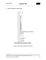
ALYSEO 106 terminal is inserted into a table box that can be installed on wall. The sizes of the
boxes are the same for all the versions and the boxes are composed by two anti-shock plastic
halfbearings and by two removable panels on the front and the rear of the box.
The front plates are provided with proper slot to make the input/output connectors and the light
signalings (LED) accessible; furthermore, the type of function and the identification of connectors
and signalings are silk-screened on the plates.
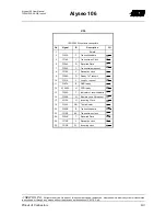
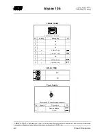
The input/output connectors present on the rear panel are the following:
•
D-SUB 9 poles female connector for the connection to PC terminal
•
Nr. 1 RJ11 6 poles female for interface to SHDSL line
•
Nr. 1 power supply bipolar male connector of power jack type
•
Nr. 1 ISO 2593 34 poles female connector for V.35 Frame Relay interface
•
Nr.2 BNC connector for the G.703 Frame Relay/ATM 75 ohm interface
•
Nr. 1 RJ45 8 poles female for G.703 Frame Relay/ATM 120ohm interface
Summary of Contents for Alyseo 106
Page 1: ...User Manual Alyseo 106 ...


