background image

Alyseo 106 

 SELTA S.p.A

All rights reserved. No parts of this document can be reproduced, memorized into archive system or transmitted 

in any shape or through any means without the previous authorization of SELTA S.p.A.


7-6 Technical 

Characteristics


Alyseo 106 User Manual 

720041008-A0-GB Issue 4 

7.3  INSULATION AND ELECTROMAGNETIC COMPATIBILITY 

The equipment is designed for use in industrial and residential environment according to the uses. 
The CE mark is released according to ETS 300 386 normative for the electromagnetic


compatibility and to the EN 60950 (2001) for the safety. 

7.3.1  Dielectric strength and insulation 

SHDSL interfaces 

1000 Vrms @ 50 Hz per 1' 

Insulation strength 

 100 M

 at 500 Vcc 35° UR<75% 

7.4 ELECTROMAGNETIC 

COMPATIBILITY 

7.4.1  Radiofrequency radiated electromagnetic fields (Emission) (EN 55022) 

Envelope 40 

dB

µ

V/m (30 

÷

 230 Mhz) @ 10 m 

 47 

dB

µ

V/m (230 

÷

 1000 Mhz) @ 10 m 

7.4.2  Electrostatic discharges (Immunity) (EN 61000-4-2) 

Envelope 

8000 V in air 


6000 V at contact 

7.4.3  Radiofrequency radiated electromagnetic fields, mod. in amp. (Immunity) (EN 61000-
4-3) 

Envelope 

10 V/m (80 

÷

 1000 MHz) 80% AM (1 kHz) 

7.4.4  Fast Transients (Immunity) (EN 61000-4-4) 

SHDSL interfaces 

500   V 5/50 ns  5 kHz 

DC power supply interfaces 

1000 V 5/50 ns  5 kHz 

RS232 interfaces 

500   V 5/50 ns  5 kHz 

V.35 interfaces 

500   V 5/50 ns  5 kHz 

2 Mbit/s interfaces 

500   V 5/50 ns  5 kHz 

7.4.5  High energy pulses (Immunity) (EN 61000-4-5) 

SHDSL interfaces 

1000 V (10/700 

µ

s) 

RS232 interfaces 

500   V (1.2/50 

µ

s) 

V.35 interfaces 

500   V (1.2/50 

µ

s) 

2 Mbit/s interfaces 

500   V (1.2/50 

µ

s) 


7.4.6  High energy pulses (Resistivity) (K.20/K21) 

SHDSL interfaces 

1000-1500/4000 V (10/700 

µ

s) 


(without/with external protection) 

Summary of Contents for Alyseo 106

Page 1: ...User Manual Alyseo 106 ...

Page 2: ...ng standards 89 336 CE EMC 73 23 CE LVD The content of this manual is ownership of SELTA which reserves the rights in compliance with the law Any reproduction modification use and diffusion of its content without written authorization are forbidden Furthermore SELTA reserves the right to modify without notice the content of this manual and rejects any responsibility for any mistakes and omissions ...

Page 3: ...2 5 2 2 5 3 Fault management protocols 2 5 2 2 6 Configuration and diagnostics 2 7 2 3 LEDS AND SIGNALINGS 2 7 3 START UP 3 1 3 1 CHECK OF MATERIAL 3 1 3 2 INSTALLATION AND POWER SUPPLY 3 1 4 CONFIGURATION INTERFACE 4 1 4 1 FOREWORD 4 1 4 2 SAVING THE CONFIGURATION 4 2 4 3 LOADING OF THE CONFIGURATION DATABASE 4 3 4 4 CHANGE OF CONFIGURATION 4 3 4 5 COMMAND SHELL 4 4 4 5 1 user modality 4 5 4 5 1 ...

Page 4: ... 1 7 1 1 ALYSEO 106 7 1 7 1 1 1 Power supply 7 1 7 1 1 2 SHDSL interface 7 1 7 1 1 3 RS232 interface to PC 7 1 7 1 1 4 V 35 interface 7 2 7 1 1 5 G 703 interface 7 2 7 2 CLIMATIC ENVIRONMENTAL CHARACTERISTICS 7 5 7 2 1 Operation 7 5 7 2 2 Storing 7 5 7 2 3 Transport 7 5 7 3 INSULATION AND ELECTROMAGNETIC COMPATIBILITY 7 6 7 3 1 Dielectric strength and insulation 7 6 7 4 ELECTROMAGNETIC COMPATIBILI...

Page 5: ... Manual 720041008 A0 GB Issue 4 9 1 1 Product safety 9 1 9 1 2 Information about the composition of products 9 2 9 2 DANGER IDENTIFICATION AND PREVENTION MEASURES 9 3 9 2 1 Common risks 9 3 9 2 2 Electrical risks 9 4 9 2 3 Fire risk 9 4 9 2 4 Mechanical risks 9 4 9 2 5 Chemical risks 9 4 9 3 TRANSPORT 9 4 9 4 ENVIRONMENTAL IMPACT 9 5 9 4 1 During the life cycle 9 5 9 4 2 Packages management 9 5 9 ...

Page 6: ... of this document can be reproduced memorized into archive system or transmitted in any shape or through any means without the previous authorization of SELTA S p A IV Contents Alyseo 106 User Manual 720041008 A0 GB Issue 4 Page intentionally left blank ...

Page 7: ...OLS IN SERVICE INTERWORKING MODALITY TRANSLATED OR TRANSPARENT MODALITY 2 4 FIGURE 2 3 ENCAPSULATION OF THE PROTOCOLS IN INTERWORKING NETWORK MODALITY 2 5 FIGURE 2 4 STATUS DIAGRAM FOR THE FAULT MANAGEMENT 2 6 FIGURE 2 5 LIGHT SIGNALINGS 2 8 FIGURE 4 1 EXAMPLE OF WEB PAGE CONFIGURE MENU 4 31 FIGURE 4 2 EXAMPLE OF WEB PAGE SHOW AND DIAGNOSTIC 4 32 FIGURE 6 1 BOX FOR ALYSEO 106 STAND ALONE 6 2 FIGUR...

Page 8: ...this document can be reproduced memorized into archive system or transmitted in any shape or through any means without the previous authorization of SELTA S p A II Index of Figures Alyseo 106 User Manual 720041008 A0 GB Issue 4 Page intentionally left blank ...

Page 9: ...this document can be reproduced memorized into archive system or transmitted in any shape or through any means without the previous authorization of SELTA S p A Index of annexes I Alyseo 106 User Manual 720041008 A0 GB Issue 4 INDEX OF ANNEXES ILL 154084017 ...

Page 10: ...this document can be reproduced memorized into archive system or transmitted in any shape or through any means without the previous authorization of SELTA S p A II Index of annexes Alyseo 106 User Manual 720041008 A0 GB Issue 4 Page intentionally left blank ...

Page 11: ...n Signal ATM Asynchronous Transfer Mode ATMF ATM Forum Bc Committed Burst size Be Excess Burst size CAC Connection Admission Control CBR Constant Bit Rate CIR Committed Information Rate CLI Command Line Interface CLP Cell Loss Priority CO Central Office CP Customer Premises CPE Customer Premises Equipment DE Discard Eligibility DLCI Data Link Connection Identifier DSL Digital Subscriber Line DSLAM...

Page 12: ...ification LTU Line Termination Unit MBS Maximum Burst Size MCT Middle Congestion Threshold MCR Minimum Cell Rate NAT Network Address Translation NIW Network InterWorking NSP Network Service Provider NTU Network Termination Unit OAM Operation And Maintenance PAM Pulse Amplitude Modulation PCR Peak Cell Rate PVC Permanent Virtual Circuit QoS Quality of Service RDI Remote Defect Indication RFC Reques...

Page 13: ...ed in any shape or through any means without the previous authorization of SELTA S p A Contents III Alyseo 106 User Manual 720041008 A0 GB Issue 4 UBR Unspecified Bit Rate plus UNI User to Network Interface VBR rt Variable Bit Rate real time VC Virtual Circuit VLAN Virtual Local Area Network VP Virtual Path WAN Wide Area Network ...

Page 14: ...document can be reproduced memorized into archive system or transmitted in any shape or through any means without the previous authorization of SELTA S p A IV Abbreviations and acronyms Alyseo 106 User Manual 720041008 A0 GB Issue 4 Page intentionally left blank ...

Page 15: ...Symmetrical singlepair High Bit Rate Digital Subscriber Line for its characteristic of allowing a digital transmission at high bit rate over the common subscriber lines The transmission takes place in a symmetrical modality so these devices are particularly indicated for business users as they find application in the realization of virtual private networks VLAN for the data transmission between fa...

Page 16: ...of this document can be reproduced memorized into archive system or transmitted in any shape or through any means without the previous authorization of SELTA S p A 1 2 Foreword Alyseo 106 User Manual 720041008 A0 GB Issue 4 Page intentionally left blank ...

Page 17: ...l support with applications of telephonic type analog voice in 0 4 KHz band The SHDSL trasmission typology is particularly innovative in fact it is possible to reach for the same performance and bit rates distances greater than the traditional DSL systems decreasing furthermore the noises present on the phone cable The real performances of the system depend on the characteristics of the twisted pa...

Page 18: ...In any case the device performances are not reduced 2 2 3 ATM Termination The Alyseo 106 terminal in the interworking applications between ATM networks and Frame Relay is a device that realizes the access to the ATM transport network implementing an ATM user interface according to ATM Forum normative UNI 3 1 and 4 0 The device supports up to 100 contemporaneous ATM connections of PVC type 1 for re...

Page 19: ...s characterized in totally independent way from the other ones by the number of DLCI s by the traffic parameters and according the service class as follows The CIR Be and Bc traffic parameters are used for DLCI to determine the policing of the incoming traffic The interval for the measurement of the traffic is calculated according to the formula T Bc CIR the frames that exceed the CIR within the i...

Page 20: ...ers from Frame Relay side DE and FECN to ATM side CLP and EFCN and viceversa can be configured according to what foreseen by the normatives Refer to 4 5 2 10 4 for the configuration details 2 2 5 1 Service interworking The management of the connections in case of SIW Frame Relay ATM is realized by the LIV Link Integrity Verification function foreseen by FRF 8 which allows to transfer the informati...

Page 21: ...ser side can be translated to a different DCLI on network side In downstream direction only in case of one to one connections all the DLCIs with value between 1 and 1022 are translated to the DLCI on user side Figure 2 3 Encapsulation of the protocols in Interworking network modality 2 2 5 3 Fault management protocols Besides the management of the Link Integrity Verification procedure foreseen by ...

Page 22: ...RDI cells to Racc CPE answer to possible LB cells in reception on ATM on i th VC PVC DOWN STATUS Problem on VC ATM CPE signals to CPE via i th LMI DLCI DOWN CPE sends 1 LB F5 cell each T1 seconds to Racc on i th VC CPE answer to possible AIS cells with RDI cells to Racc CPE answer to possible LB cells in reception on ATM on i th VC UP RETRY STATUS Problem on VC ATM CPE sends 1 LB F5 cell each T2 s...

Page 23: ...erface from the connected terminal through the serial interface RS232 present on the device or from remote through the same interface via telnet by means of a web browser and via SNMP manager communicating with an agent present on terminal The connections from remote can be configured both for access from local network typically from a PC on LAN that reaches the Frame Relay port of the Alyseo 106 ...

Page 24: ...morized into archive system or transmitted in any shape or through any means without the previous authorization of SELTA S p A 2 8 Overview Alyseo 106 User Manual 720041008 A0 GB Issue 4 LED 2Mbit s AL Red LED that lits in case of alarms on G 703 G 704 interface Figure 2 5 Light signalings ...

Page 25: ...d elements are contained 3 2 INSTALLATION AND POWER SUPPLY 1 Verify that the room complies with what described in Climatic environmental characteristics 2 Check that the main power supply is 220 240 Veff 6 10 of tolerance 50Hz 3 Connect the output of the AC DC converter to the proper power jack on the rear panel If necessary set the provided anti tearing band 4 Connect the AC DC converter to the 2...

Page 26: ...of this document can be reproduced memorized into archive system or transmitted in any shape or through any means without the previous authorization of SELTA S p A 3 2 Start up Alyseo 106 User Manual 720041008 A0 GB Issue 4 Page intentionally left blank ...

Page 27: ...hyperterminal on Windows operating system it is possible to access to the command shell which requires two passwords The first one is for normal users user and the second one is for users enabled to configure the Alyseo 106 superuser The pre stored password is selta for both ones but they can be modified for the users in priviliged modality By means of CLI the device can be configured the firware ...

Page 28: ...e of power supply missing due to accidental events it allows the complete restore of the machine within the user network The possible commands with the brief description on video are Alyseo106 save rom save to internal rom memory serial save configuration to PC from serial IMPORTANT The user and superuser access passwords are saved in encrypted way together with the configuration of Alyseo 106 bec...

Page 29: ...h memory by means of its dual command save rom load serial It allows loading the configuration previously saved via serial line see the following example load http It is possible to re load a given configuration also via http properly specifying the URL where the updating software is stored This option is available if a control channel has been properly configured The use of the commands described...

Page 30: ...echoed on video and the commands available on this level with a brief description will be automatically listed on the screen otherwise if a command has been already typed the sub commands supported by this one will be listed Continue in this way until typing the writing ENTER no further known parameters is not displayed on video that is no other parameters are necessary for the command string inse...

Page 31: ...g to the level have different sub commands In this case the tree is Alyseo106 show running config Current operating configuration diagnostic diagnostic parameter interfaces Show statistics interfaces system system information uptime How time Alyseo works memory Memory statistics ramdisk Show ramdisk statistics interrupts Number of interrupts processed cpu CPU Information privilege Show current pri...

Page 32: ... Alyseo 106 An example for the application of interworking function is reported Alyseo106 show diagnostics IWF shdsl show shdsl diagnostic atm show atm diagnostic frame_relay show frame relay diagnostic iwf show interworking function diagnostics cf show cell forwarding diagnostic enter show all diagnostic Here below a typical example of control of packet counters on the frame relay interface is di...

Page 33: ...e R1 10 Alyseo106 show diagnostic frame_relay 102 Frame Relay Endpoint DLCI 102 IWF Connection Index 1 in Congestion Discard 0 in DE Congestion Discard 0 in DE Frames 0 in Discards 0 in Discard DE set 0 in Frames 100 in Frames BECN set 0 in Frames FECN set 0 out Congestion Discard 0 out DE Congestion Discard 0 out DE Frames 0 out Frames 100 out Frames BECN set 0 out Frames FECN set 0 FR PVC Status...

Page 34: ...X Loop 223 OAM Cells F5 End to End TX RDI 0 OAM Cells F5 Segment RX AIS 0 OAM Cells F5 Segment RX Loop 0 OAM Cells F5 Segment RX RDI 0 OAM Cells F5 Segment TX AIS 0 OAM Cells F5 Segment TX Loop 0 OAM Cells F5 Segment TX RDI 0 PDUs CRC errors 0 Over Sized SDUs 0 Sar TimeOuts 0 Alyseo106 show diagnostic iwf IWF Diagnostic IWF 1 DLCI 102 VPI 8 VCI 35 Atm to Frame Relay Oper Status up Frame Relay to A...

Page 35: ... counters enable Enter administrator mode ping Send echo messages atmping Send echo messages over OAM cell telnet Open a telnet connection load Load configuration and reboot save Save configuration reboot Reboot system upgrade upgrade firmware version secret Set authentication secrets exit Exit cish session 4 5 2 1 clear menu It allows the reset of the counters used in the diagnostic of alyseo 106...

Page 36: ...ee End to End seg Segment by this selection the first atm node will answer in case Segment and the last will answer in case End to End is selected In case of f5 the choice is the same 4 5 2 4 telnet menu It allows opening a telnet session on a remote machine whose IP address is known 4 5 2 5 load menu See chapter 4 3 of this manual 4 5 2 6 save menu See chapter 4 2 of this manual 4 5 2 7 reboot co...

Page 37: ...type of application Through this configuration it is possible to select the terminal application between Interworking Function and Cell Forwarding The switching from one application to the other one causes the saving to ROM of the configuration and the terminal reboot In the following paragraphs 4 5 2 10 and 4 5 2 11 the configuration parameters of the two applications are reported 4 5 2 10 config...

Page 38: ...e configured accessing the line and driver submenu this one is meaningful only for 4 wire modality the configurable parameters can depend on the DSLAM which the terminal is connected to The 2 or 4 wire modality is available only on terminals of code 680452029 provided with double SHDSL interface Alyseo106 configure shdsl Alyseo106 shdsl conf mode Central Office or Customers Premises Equipment rate...

Page 39: ... 2048 Rate1 2048 Kb s Finally CTRL D or done to come back to upper level 4 5 2 10 2 Frame Relay The commands available at this level are Alyseo106 configure frame_relay Alyseo106 fr conf port configure Frame Relay port endpoint configure Frame Relay End Point Usage endpoint dlci lmi LMI Local Management Interface parameter no Negate a configuration item show Show Frame Relay Configuration done Don...

Page 40: ...seo106 fr port conf service FR V35 Port ITU T G 703 FR E1 Serial Port V35 Once this configuration is made the parameters specific of the chosen interface are accessed The passage from one type of interface to another one causes the reboot of the terminal after the saving of the configuration to ROM The menu opens to configure the following parameters of the V35 physical port Alyseo106 fr port conf...

Page 41: ... conf type unframed E1 unframed only n 32 framedCRC4 E1 framed with CRC4 1 n 31 framedNOCRC4 E1 framed without CRC4 1 n 31 Speed selects the number of used Time Slots Alyseo106 fr port E1 conf speed 64 2048 port speed n 64 n 1 31 E1 framed n 32 E1 unframed The clock can be locally generated or taken by the received data Alyseo106 fr port E1 conf clock local Tx clock generated in local fromRX Tx cl...

Page 42: ...tion Identifier it is possible to create a new FR connection and configure it or to modify an existing one If a non existing value of DLCI is inserted CLI asks for confirmation before creating it type y or yes to confirm Ex Alyseo106 fr conf endpoint 16 1007 dlci value Alyseo106 fr conf endpoint 200 dlci not exist Insert new DLCI yes or no yes DLCI 200 inserted This command has changed level and n...

Page 43: ... Interfaces parameter show Show Frame Relay Configuration done Done Frame Relay configuration LMI LMI item opens a submenu dedicated to signaling of Frame Relay typing LMI and as we did before the following submenu opens Alyseo106 fr lmi procedure local in channel signaling procedural role type Signaling Protocol N391 full status polling cycle value N392 error threshold value N393 monitored events...

Page 44: ...on Interface Alyseo 106 User Manual 720041008 A0 GB Issue 4 none Interface does not use a PVC signaling protocol annexA Interface operates the ITU Q 933 Annex A PVC status protocol annexD Interface operates the ANSI T1 617 Annex D PVC status protocol cisco Interface operates the Cisco PVC status protocol The other parameters refer to the respective signaling protocols on Frame Relay channel and th...

Page 45: ...m show Show ATM configuration done Done ATM configuration The pvc item allows configuring the parameters of an existing pvc or inserting a new one It is necessary to insert the vci and the vpi of pvc The user is guided in the insertion on the parameters typing after each value Ex Alyseo106 atm conf pvc 0 255 VPI value expected value of vpi insert 8 as vpi followed by Alyseo106 atm conf pvc 8 32 25...

Page 46: ...fied Bit Rate Exiting from the menu related to traffic descriptor by means of the show atm command it is possible to display the configured pvc and the related associated traffic descriptors CAC It is possible to enable the control of the connections on ATM enabling the CAC item The calculation is made according to the configured Band_dsl band value independently from the real bit rate of the SHDS...

Page 47: ...ing the iwf command followed by the endpoint frame relay and by the pvc atm it is possible to modify an existing iwf or to create a new one The iwf section deals also with the passing of the atm parameters to frame relay and viceversa It is possible to force the CLP Cell Loss Priority value in mapping on DE Discard Elegibility and viceversa It is also possible to manage the two transmission modali...

Page 48: ... parameters on pvc descriptor_index It allows the modification of the parameters of the mapping of DLCI on pvc managed It enables the transmission of the signaling cells Link Integrity Verification OAM on the selected pvc nomanaged It disables the transmission of the signaling cells Link Integrity Verification OAM on the selected pvc through the iwf where you entered show It displays all the iwf p...

Page 49: ...ss endpoint Frame Relay channel control Usage endpoint DLCI pvc ATM channel control Usage VPI VCI route manipulate the IP routing table delete Delete a channel control show show access control done done control configuration In details none This command allows disabling all the data ports of alyseo as the following example shows Alyseo106 access control none Alyseo port access OFF result of the co...

Page 50: ...and then re enable only http and ftp Alyseo106 access control none Alyseo port access OFF all the ports are disabled Alyseo106 access control http on HTTP ON http port is enabled Alyseo106 access control ftp on FTP ON ftp port is enabled endpoint It allows realizing a control DLCI in such a way to have an IP address associated and to operate as Frame Relay endpoint Ex Alyseo106 access control endp...

Page 51: ... destination address where a subnet of 10 0 2 0 type with netmask 255 255 255 0 is specified 4 5 2 11 configure CF menu The Application CF choice allows accessing to the configuration of Cell Forwarding Alyseo106 configure CF Alyseo106 configure shdsl SHDSL link parameter cf pvc Create or modify cross connect for CF cntrl Access control show Show running configuration commit Active configuration d...

Page 52: ... ADMIN STATUS 1 VP 1 x 1 x 1920 cbr up 2 VC 2 32 4 34 19208 ubr up CAC disabled CAC Upper Bound 1920 Kb s 4 5 2 11 2 Addition of entries to the table of ATM switch The deletion of a cross connection is made specifying in the delete command the index as it appears in the show pvc table In this way all the parameters of the connection are deleted Alternatively it is possible to set the administrativ...

Page 53: ... 1920 ubr down CAC disabled CAC Upper Bound 1920 Kb s 4 5 2 11 3 Configuration of Control Admission Control It is possible to enable the CAC on the connections specifying the band limit in Kbit s as follows The band limit is defined before and it is necessary to verify that it is in compliance with line bit rate set on exchange side on the access multiplex Alyseo106 cf conf CAC enable CAC enable d...

Page 54: ...ype framedCRC4 E1 framed with CRC4 1 n 31 framedNOCRC4 E1 framed without CRC4 1 n 31 Alyseo106 cf port E1 conf type framedCRC4 Line E1 Framed with CRC Alyseo106 cf port E1 conf type framedNOCRC4 Line E1 Framed Enabling of the scrambling of the header of the ATM cell enabled by default Alyseo106 cf port E1 conf hec enable disable Enabling of the scrambling on the ATM payload meaningful only for end...

Page 55: ... for the interworking function in 4 5 2 10 4 4 5 2 12 Diagnostics menu for the Cell Forwarding application The diagnostics parameters accessible from the following menu for the application are reported here below for the ATM and IWF diagnostics a warning message is displayed as they are relevant to the interworking function Alyseo106 show diagnostic shdsl show shdsl diagnostic atm show atm diagnos...

Page 56: ... release R1 10 Alyseo106 show diagnostic cf CF Diagnostic E1 side Cell Swtd E1 interface SHDSL side Cell Swtd SHDSL nterface VPI VCI toSHDSL BadHec CLPset Dropped VPI VCI to E1 BadHec CLPset Dropped 4 34 0 2 32 0 TOTAL 0 0 0 0 0 0 0 0 Alyseo106 show interfaces utopia_stat ENTER no further known parameters Alyseo106 show interfaces utopia_stat Itf Type ESI MAC addr AAL TX err RX err drop 0 utopia 0...

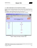
Page 57: ...ENT VIA THE INTEGRATED HTTP SERVER By means of the control channel then from both the user FR side and the network ATM side it is possible to access to diagnostic configuration sessions through a http connection using a web browser The meaning of the parameters and the logic used in the configuration from CLI is kept unchanged for example when adding and removing a connection etc In the following ...

Page 58: ...agement are on the left side of the screen but not all the commands possible on serial line are possible also via http server http in particular the following configurations cannot be accessed Enabling disabling of the remote service http telnet snmp Change of IP addresses control interfaces and static routes Enabling of loops on Frame Relay and SHDSL side Password change Remember to execute the c...

Page 59: ... 106 2 WIRE TERMINAL 680452028 A0 GB ALYSEO 106 4 WIRE TERMINAL 680452029 A0 GB 5 2 LIST OF OPTIONAL PARTS NAME CODE 9 POLES MALE 9 POLES FEMALE CORD FOR LOCAL ACCESS TERMINAL 154084017 D SUB 9 POLES MALE CONNECTOR WITH CAP 390190000 D SUB 9 POLES FEMALE CONNECTOR WITH CAP 390190001 230 Vac 12Vcc 10 W POWER SUPPLY with cable and power supply connector 645030010_A0_GB PERSONAL COMPUTER FOR LOCAL MA...

Page 60: ...rchive system or transmitted in any shape or through any means without the previous authorization of SELTA S p A 5 2 List of Codes Alyseo 106 User Manual 720041008 A0 GB Issue 4 5 4 LIST OF SOFTWARE NAME CODE Bootstrap firmware of alyseo 106 aly106_b 658600016 Software alyseo 106 aly106_r 658600008 A0 GB ...

Page 61: ... and by two removable panels on the front and the rear of the box The front plates are provided with proper slot to make the input output connectors and the light signalings LED accessible furthermore the type of function and the identification of connectors and signalings are silk screened on the plates The input output connectors present on the rear panel are the following D SUB 9 poles female c...

Page 62: ...ugh any means without the previous authorization of SELTA S p A 6 2 Mechanical Structure and Installation Alyseo 106 User Manual 720041008 A0 GB Issue 4 6 2 SHAPE AND SIZE Figure 6 1 Box for Alyseo 106 stand alone CONNECTORS SIDE HOUSING FOR POSSIBLE RUBBER FEET RUBBER FEET LED SIDE LIGHT GUIDE WHICH CONTINUES ALSO ON THE FRONT SIDE VENTILATION OPENING ...

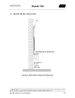
Page 63: ...rasmessa in qualsiasi forma o mezzo senza la preventiva autorizzazione della SELTA S p A Mechanical Structure and Installation 6 3 Alyseo 106 User Manual 720041008 A0 GB Issue 4 6 3 POSITION AND WALL INSTALLATION Figure 6 2 Wall position of Alyseo 106 stand alone Superimposed in perspective Power supply 12 V V 35 cable G 703 cable SHDSL cable ...

Page 64: ...chanical Structure and Installation Alyseo 106 User Manual 720041008 A0 GB Issue 4 6 4 PRESETTING FOR WETTING CURRENT Figure 6 3 Wetting current presetting Jumper Line Position Modality JP1 1 O Twisted pair 1 in open circuit JP1 1 W Presetting for the wetting current on twisted pair 1 JP2 2 O Twisted pair 2 in open circuit JP2 2 W Presetting for the wetting current on twisted pair 2 Default config...

Page 65: ...vercurrent I 10 In In nominal absorbed current Consumption dissipation 8 W Input Output insulation 1000 Vrms 7 1 1 2 SHDSL interface Payload 192 2304 Kbit s step 64 Kbit s Line coding TC 16 PAM Band width 292 kHz Spectrum 0 1000 kHz bandwidth at 40 dB Transmission distance 25 dB 2048 Kbit s according ETSI TS 101 524 Max transmission power 14 5 dBm 13 5 dBm Termination impedance 135 Ω nominal Retur...

Page 66: ...pe according to V 36 with V 35 connector Connector ISO 2593 34 poles female Managed signals C102 C102a C102b C103 C104 C105 C109 C114 C115 V 11 C106 C107 C109 C142 driver V 10 with common return C140 C141 receiver V 10 cat 2 Bit rate Nx64 kbit s N 1 32 36 7 1 1 5 G 703 interface TRANSMISSION Line code HDB3 Pulse according to G 703 75 120 Ω Nominal Impedance 75 120 Ω RECEPTION Line code HDB3 Nomina...

Page 67: ...A Technical Characteristics 7 3 Alyseo 106 User Manual 720041008 A0 GB Issue 4 MASK OF JITTER ACCEPTANCE AT 2048 kHz ETSI TS 101 135 f 1 f 2 f 3 f 4 f 0 A 1 A 2 A Pendenza di 20 dB decade Frequenza scala logaritmica Ampiezza picco picco del jitter e wander scala logaritmica 0 Figure 7 1 Mask for jitter acceptance Peak peak width of jitter and wander logarithmic scale 20 dB decade slope Frequency l...

Page 68: ...pp UIpp µHz Hz Hz kHz kHz Table 7 B Jitter generated at 2 Mbit s unstructured Max allowed jitter Parameters of band pass filter high pass has a first order slope Parameter B1 f1 f4 B2 f3 f4 f1 f3 f4 Value 0 3 0 15 20 700 100 Unit UIpp UIpp Hz Hz kHz 2 Mbit s STRUCTURED Table 7 C Jitter accepted at 2 Mbit s structured Peak peak width Frequency Parameter A0 A1 A2 f0 f1 f2 f3 f4 Value 1 35 0 18 20 24...

Page 69: ...out the previous authorization of SELTA S p A Technical Characteristics 7 5 Alyseo 106 User Manual 720041008 A0 GB Issue 4 7 2 CLIMATIC ENVIRONMENTAL CHARACTERISTICS 7 2 1 Operation Temperature range 5 45 C Relative humidity da 5 a 95 7 2 2 Storing Temperature range 40 70 C Relative humidity da 5 a 95 7 2 3 Transport Temperature range 40 70 C Relative humidity da 5 a 95 ...

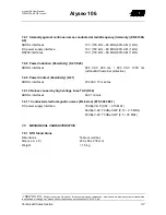
Page 70: ...NETIC COMPATIBILITY 7 4 1 Radiofrequency radiated electromagnetic fields Emission EN 55022 Envelope 40 dBµV m 30 230 Mhz 10 m 47 dBµV m 230 1000 Mhz 10 m 7 4 2 Electrostatic discharges Immunity EN 61000 4 2 Envelope 8000 V in air 6000 V at contact 7 4 3 Radiofrequency radiated electromagnetic fields mod in amp Immunity EN 61000 4 3 Envelope 10 V m 80 1000 MHz 80 AM 1 kHz 7 4 4 Fast Transients Immu...

Page 71: ...50 kHz 80 MHz 80 AM 1 kHz RS232 interfaces 10 V 150 kHz 80 MHz 80 AM 1 kHz 7 4 8 Power Induction Resistivity K 21 K20 SHDSL interfaces 600 VAC 200 ms 600 VAC 1000 ms without with external protection 7 4 9 Power Contact Resistivity K 21 SHDSL interfaces 230 VAC 15 minutes 7 4 10 Noises caused by high voltage lines TAV K 54 SHDSL interfaces 60V 1 minute 7 4 11 Conducted electromagnetic noises Emissi...

Page 72: ...document can be reproduced memorized into archive system or transmitted in any shape or through any means without the previous authorization of SELTA S p A 7 8 Technical Characteristics Alyseo 106 User Manual 720041008 A0 GB Issue 4 Page intentionally left blank ...

Page 73: ...Pinout of Connectors 8 1 Alyseo 106 User Manual 720041008 A0 GB Issue 4 8 PINOUT OF CONNECTORS Figure 8 1 Description of Connectors CONNECTOR DESCRIPTION SHDSL SHDSL interface TERMINAL Interface for maintenance local terminal V 35 Connection of DTE device to V 35 Frame Relay interface POWER SUPPLY Device power supply connector 2 Mbit s 120Ω G 703 interface at 2Mbit s 120Ω 2 Mbit s 75Ω G 703 interf...

Page 74: ...LTA S p A 8 2 Pinout of Connectors Alyseo 106 User Manual 720041008 A0 GB Issue 4 SHDSL interface RJ11 6 poles F connectors Pin Polarity Description I O 1 2 a SHDSL2 3 a SHDSL 1 4 b SHDSL1 5 b SHDSL2 6 Terminal interface D SUB DIN 41652 9 contacts F connectors Pin Signal Description I O 1 2 C104 Received data 3 C103 Transmitted data 4 C108 Data Terminal Ready DTR 5 C102 GND 6 C107 Data Set Ready D...

Page 75: ...ignal ID Description I O 1 Shield 4 C103A P Transmitted data 5 C114A Y Transmission Clock 6 C104A R Received Data 7 C105A C Transmission request 8 C115A V Reception clock 9 C106A D Ready To Transmit 10 C141A L Loop 3c request 11 C107A E DSR ready 12 C108 2A H DTR ready 13 C109A F Indicator of received data 14 C140A N Remote Loop 2b request 17 C113A U Incoming Clock 18 C142A NN Test indicator 22 C1...

Page 76: ... of SELTA S p A 8 4 Pinout of Connectors Alyseo 106 User Manual 720041008 A0 GB Issue 4 2 Mbit s 120Ω Ω Ω Ω 1 8 RJ45 8 poles F connector Pin Polarity Description I O 1 Nc 2 Nc 3 Nc 4 b 2 Mbit s Tx tip 5 a 2 Mbit s Tx ring 6 Nc 7 a 2 Mbit s Rx tip 8 b 2 Mbit s Rx ring 2 Mbit s 75Ω Ω Ω Ω RX TX Power Supply Power Jack 5 5 2 1 power supply connector Pin Segnale Descrizione I O 1 2 Service battery 12 V...

Page 77: ...en This chapter focuses on the compliance of the equipment to the safety standards along with the instructions aimed to avoid any possible risk arising from the improper use of the equipment itself The indications contained in the following chapter are grouped as follows product safety product composition danger detection and measures to prevent dangers first aid in case of electric shock shipping...

Page 78: ...3 2 2000 title Electromagnetic compatibility EMC Part 3 2 Limits Limits for harmonic current emissions equipment input current up to and including 16 A per phase 9 1 2 Information about the composition of products The product present an electronic structure Depending on the required typology and customization the products can present with a single steel or plastic case where the electronic cards a...

Page 79: ...tions reported on them In case of devices sensitive to electrostatic discharges identified by one of the symbol below it is necessary to handle them using all the measures suitable to reduce the risks deriving from the accumulation of electrostatic discharges In this case use a protection constituted by an antistatic wristband and by a coiled cord to be used in the following way The antistatic wri...

Page 80: ... vapours can be generated as product residual when this element reaches high temperatures above 500 C these vapours are toxic if inhaled some products used to build the equipment can generate fumes and vapours dangerous for health In case of fire the extinguishing extinction must be realized by qualified personnel with the possible use of respirators aprovide a good ventilation of the rooms after ...

Page 81: ...e managed giving priority as possible to re use recycling or as last solution the disposal These activities must be executed by means of bodies authorized to this purpose For a correct management of the packing materials after their use follow the CER classification paper board 150101 wood pallet 150103 plastic film plastic foam polystyrene thermoplastic material 150102 9 4 3 End of life cycle pro...

Page 82: ...t can be reproduced memorized into archive system or transmitted in any shape or through any means without the previous authorization of SELTA S p A 9 6 Technical Notes for Human and Environmental Safe Use Alyseo 106 User Manual 720041008 A0 GB Issue 4 End of document ...

Page 83: ...9P F D SUB DIN 41652 9P M 9P F D SUB DIN 41652 CONNECTOR RS 232 CABLE Codice Code 154084017 Impiego cavo per interfaccia RS 232 Use RS 232 interface cable Connettore C1 9P F Connettore C2 9P M Connector C1 9P F Connector C2 9P M DA from A to Descrizione Segnali signal description 1 C1 1 C2 CD Carrier Detector 2 C1 2 C2 RD Received Data 3 C1 3 C2 TD Transmited Data 4 C1 4 C2 DTR Data Terminal Ready...

Reviews: