background image


NCA-4035


User Manual


Version: 1.0 

Date of Release: 2022-11-03 

Network Appliance Platforms 

Summary of Contents for NCA-4035

Page 1: ...1 NCA 4035 User Manual Version 1 0 Date of Release 2022 11 03 Network Appliance Platforms ...

Page 2: ...ter As certain categories of documents are only available to users who are logged in please be registered for a Lanner Account at http www lannerinc com to access published documents and downloadable resources In addition to contacting your distributor or sales representative you could submit a request at our Lanner Technical Support and fill in a support ticket to our technical support department...

Page 3: ...ad Huilongguan Town Changping District Beijing 102208 China T 86 010 82795600 F 86 010 62963250 E service ls china com cn USA Lanner Electronics Inc 47790 Westinghouse Drive Fremont CA 94539 T 1 855 852 6637 F 1 510 979 0689 E sales_us lannerinc com Canada Lanner Electronics Canada Ltd 3160A Orlando Drive Mississauga ON L4V 1R5 Canada T 1 877 813 2132 F 1 905 362 2369 E sales_ca lannerinc com Euro...

Page 4: ...t not be co located or operating in conjunction with any other antenna or transmitter Follow these guidelines to ensure general safety Keep the chassis area clear and dust free during and after installation Do not wear loose clothing or jewelry that could get caught in the chassis Fasten your tie or scarf and roll up your sleeves Wear safety glasses if you are working under any conditions that mig...

Page 5: ...placez l appareil Electrical equipment generates heat Ambient air temperature may not be adequate to cool equipment to acceptable operating temperatures without adequate circulation Be sure that the room in which you choose to operate your system has adequate air circulation Ensure that the chassis cover is secure The chassis design allows cooling air to circulate effectively An open chassis permi...

Page 6: ...deration of equipment nameplate ratings should be used when addressing this concern Reliable Grounding Reliable grounding of rack mounted equipment should be maintained Particular attention should be given to supply connections other than direct connections to the branch circuit e g use of power strips Installation Operation This equipment must be grounded The power cord for product should be conn...

Page 7: ...onnexion à la terre est très importante pour protéger l équipement contre les effets néfastes du bruit externe et réduire les risques d électrocution en cas de foudre Pour désinstaller l équipement débranchez le câble de mise à la terre après avoir éteint l appareil Un câble de mise àla terre est requis et la zone reliant les sections du conducteur doit faire plus de 4 mm2 ou 10 AWG Connect the gr...

Page 8: ...ock Diagram 14 Jumpers and Connectors 15 Opening the Chassis 29 Installing the System Memory 30 Installing M 2 Memory Cards Optional 32 Installing IPMI BMC Card Optional 34 Installing TPM 35 Installing NIC Modules 36 Replacing the Power Supply Units 37 Mounting the System 38 Overview 44 BMC Main Features 44 BMC Firmware Functional Description 45 ...

Page 9: ...nds Support List 46 Using BMC Web UI 48 Wizard Welcome Page Introduction 50 Web UI Layout Introduction 51 Main Page 54 Advanced 55 Platform 75 Socket 79 Server Mgmt 90 Security 95 Boot Menu 98 Save and Exit Menu 99 Warranty Policy 108 ...

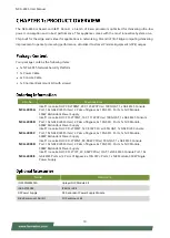
Page 10: ...1x NIC Module 300W Redundant Power Supply NCA 4035B Intel Ice Lake D HCC D 2776NT 16C 117W CPU w 100G QAT 1x GbE RJ45 Console Port 10x GbE RJ45 Ports w 2 Pairs of Bypass 4x 10G SFP Ports 1x NIC Module 300W Redundant Power Supply NCA 4035C Intel Ice Lake D HCC D 2753NT 12C 87W CPU w 50G QAT 1x GbE RJ45 Console Port 10x GbE RJ45 Ports w 2 Pairs of Bypass 4x 10G SFP Ports 1x NIC Module 300W Redundant...

Page 11: ...us Storage refer to Appendix A Power Button 1x ATX Power Button Console Port 1x RJ45 Consol Port USB Port 2x USB 3 0 Ports Power Input 1x AC Power Inlet on PSU Storage Onboard Slots 1x M 2 2242 B Key 2x M 2 2280 B Key Expansion PCIe 1x Gen4 PCI E 8 for front NIC via 1x SlimSAS connector 1x Gen4 PCIe 16 for Rear Standard PCIe card via 2x Slim SAS Connector FHHL Miscellaneous Watchdog Yes Internal R...

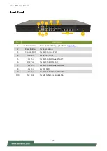
Page 12: ...et Button F3 Console Port 1x RJ45 Console Port F4 USB Port 2x USB 3 0 Ports F5 LAN Port 1x RJ45 GbE LAN via I210 AT F6 LOM Port 1x RJ45 GbE LOM Port F7 LAN Port 4x RJ45 GbE LAN via I350 AM4 F8 LAN Port 4x 10G SFP F9 LAN Port 4x RJ45 GbE LAN via I350 AM4 F10 NIC Slot 1x NIC NCS2 Slim Module Slot F5 F1 F3 F7 F4 F2 F8 F9 F10 F6 ...

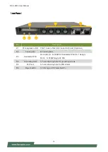
Page 13: ...tional R2 Cooling Fan 4x Cooling Fans R3 Redundant PSU SKU A B C D 2x 300W AC Redundant PSU N 1 design SKU E 1x 350W Single AC PSU R4 Grounding Hole 1x Semi shearing hole for grounding screws R5 ESD Jack 1x Semi shearing hole for ESD screws R6 Power Switch 1x Slim Type ATX Power Switch R1 R3 R4 R6 R2 R5 ...

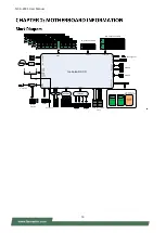
Page 14: ...nsole USB3 0 2x M 2 2280 SATA SSD eSPI 80 debug ports SATA3 0 M 2 2242 SATA SSD SPI SPI ROM BIOS BIOS PCIe USB LPC GPIO ADC UART others NCSI I210 I210 I350 AM4 1x PCIEx4 4x10G SFP or 2x25G SFP28 SlimSAS 1xPCIex16 or 2xPCIex8 4xSGMII or SFI 4 Port 1G 4x10G Maxlinear 4x2 5G XL827 88E1543 1xPCIex8 SlimSAS Intel not support Lanner should request Bypass Bypass ...

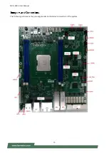
Page 15: ...NCA 4035 User Manual 15 The following references the pin assignments and internal connectors of the system ...

Page 16: ...iption 1 2 Hardware Reset 2 3 Software Reset JDUAL1 Select CS for Flash Fixture Pin Switch Description 1 2 Short 3 4 Short Flash 1st SPI ROM Default 1 3 Short 2 4 Short Flash 2nd SPI ROM J13 BIOS Boot Up Function Select Pin Switch Description 1 3 Short Boot Up from 1st SPI ROM Default 3 5 Short Boot Up from 2nd SPI ROM Pin Switch Description 2 4 Short Enable Dual BIOS Default 4 6 Short Disable Dua...

Page 17: ...8 MD3 8 T78 MD3 10 100 1000 10 10 100 1000 11 Link ACT 12 Link ACT LAN1 2x2 Port RJ 45 with LED Pin No Description Fast E Net Giga Net N1 TX MD0 2 TX MD0 3 RX MD1 4 T45 MD2 5 T45 MD2 6 RX MD1 7 T78 MD3 8 T78 MD3 10 100 1000 10 10 100 1000 11 Link ACT 12 Link ACT LAN2 1x4 Port RJ 45 with LED Pin No Description Fast E Net Giga Net N1 TX MD0 2 TX MD0 ...

Page 18: ...scription 1 VeeT 11 VeeR 2 TxFault 12 RD 3 TxDis 13 RD 4 SDA 14 VeeR 5 SCL 15 VCCR 6 MOD_ABS 16 VCCT 7 RS0 17 VeeT 8 RX_LOS 18 TD 9 RS1 19 TD 10 VeeR 20 VeeT JLAN1 Minimezz Connector PIN Description PIN Description 1 5VSB 2 GND 3 NC 4 CR_RX0 5 NC 6 CR_RX0 7 GND 8 GND 9 CR_RX1 10 NC 11 CR_RX1 12 NC 13 GND 14 GND 15 NC 16 CR_RX2 17 NC 18 CR_RX2 19 GND 20 GND 21 CR_RX3 22 NC 23 CR_RX3 24 NC ...

Page 19: ...38 12VSB 39 NC 40 MDC 41 NC 42 INT 43 GBE_SCL 44 GBE_RST 45 GBE_SDA 46 GND 47 NC 48 CR_TX0 49 NC 50 CR_TX0 51 GND 52 GND 53 CR_TX2 54 NC 55 CR_TX2 56 NC 57 GND 58 59 NC 60 CR_TX1 61 NC 62 CR_TX1 63 GND 64 GND 65 CR_TX3 66 NC 67 CR_TX3 68 NC 69 GND 70 GND 71 NC 72 NC 73 NC 74 NC 75 GND 76 GND 77 GND 78 GND 79 12VSB 80 12VSB ...

Page 20: ...sole Port Connector PIN Description 1 NC 2 NC 3 NC 4 GND 5 TXD 6 RXD 7 RTS 8 CTS PIN Description 1 USB_VCC1 2 D1 3 D1 4 GND 5 USB3 0_RX 6 USB3 0_RX 7 GND 8 USB3 0_TX 9 USB3 0_X JCOM2 COM2 Pin Header PIN Description 1 DCD 2 DSR 3 RX 4 RTS 5 TX 6 CTS 7 DTR 8 RI 9 GND ...

Page 21: ...E_RX3P A12 PCIE_TX2N B12 PCIE_RX3N A13 GND B13 GND A14 PCIE_TX3P B14 PCIE_RX4P A15 PCIE_TX3N B15 PCIE_RX4N A16 GND B16 GND A17 PCIE_TX4P B17 PCIE_RX5P A18 PCIE_TX4N B18 PCIE_RX5N A19 GND B19 GND A20 PCIE_TX5P B20 PCIE_RX6P A21 PCIE_TX5N B21 PCIE_RX6N A22 GND B22 GND A23 PCIE_TX6P B23 PCIE_RX7P A24 PCIE_TX6N B24 PCIE_RX7N A25 GND B25 GND A26 PCIE_TX7P B26 PCIE_CLK1P A27 PCIE_TX7N B27 PCIE_CLK1N A28...

Page 22: ...11 21 P3V3_ADC9 GPIX1 22 BMC_UART_RXD 23 RSVD4 24 BMC_UART_TXD 25 GND2 26 GND33 27 I2C_SDA6 GPIOK3 28 ADC2 GPIW2 29 I2C_SCL6 GPIOK2 30 ADC3 GPIW3 31 GND3 32 ADC8 GPIX0 33 I2C_SDA7 GPIOK5 34 GND34 35 I2C_SCL7 GPIOK4 36 SYS_UART1_DSR 37 GND4 38 SYS_UART1_TXD 39 SYS_UART1_DCD 40 SYS_UART1_RXD 41 SYS_UART1_CTS 42 SYS_UART1_RI 43 GND5 44 SYS_UART1_DTR 45 PWM5 GPION5 46 SYS_UART1_RTS 47 PWM3 GPION3 48 G...

Page 23: ... 97 GPIOZ1 NORA1 SIOPWRGD 98 GPIOZ0 NORA0 SIOPB 99 GPIOZ2 NORA2 SIOPBO 100 GPIOS0 SPI2CS1 101 GPIOZ3 NORA3 SIOSCI 102 GPIOS1 BMCINT 103 GPIOAB1 NORWE 104 GPIOS3 SALT6 105 GPIOAB2 WDTSRT1 106 GPIOAB0 NOROE 107 SYS_SLP_S5_IN 108 GPIOAB3 WDTSRT2 109 SYS_SLP_S3_IN 110 EXTRST 111 GPIOY3 SIOONCTRL 112 PEWAKE GPIOQ7 113 BMC_SPI_SWITCH_OUT 114 GND41 115 I2C_SCL14_IPMIB2 116 I2C_SDA1_Thermail Sensors HW_mo...

Page 24: ...CPU_CATERR_IN 161 MDIO2 GPIOA7 TIMER8 162 BMC_UART_SWITCH_OUT 163 SYS_RSMRST_IN 164 GND48 165 GND19 166 CPU_THERMTRIP_IN 167 ESPI_RESET 168 BMC_RSTBTN_OUT 169 LSIRQ ESPIALT GPIOAC6 170 SYS_PWROK_IN 171 ESPI_ALERT 172 CPU0_PROCHOT_IN 173 GND20 174 CPU0_FIVR_FAULT_IN 175 LPCRST ESPIRST GPIOAC7 176 BMC_SPKR_OUT 177 LFRAMEN ESPICS GPIOAC5 178 CPU1_FIVR_FAULT_IN 179 LAD1 ESPID1 GPIOAC1 180 GND49 181 LA...

Page 25: ...RXCK RMII2RCLKI GPIOV2 221 MDI0N 222 RGMII2RXCTL GPIOV3 223 GND25 224 RGMII2RXD2 RMII2CRSDV GPIOV6 225 MDI1P 226 RGMII2RXD1 RMII2RXD1 GPIOV5 227 MDI1N 228 GND55 229 GND26 230 MAC2 STRAP 231 MDI2P 232 RGMII2TXD3 GPIOU3 233 MDI2N 234 RGMII2TXCK RMII2RCLKO GPIOT6 235 GND27 236 RGMII2TXD0 RMII2TXD0 GPIOU0 237 MDI3P 238 RGMII2TXD2 GPIOU2 239 MDI3N 240 RGMII2TXCK RMII2RCLKO GPIOT7 241 GND28 242 RGMII2TX...

Page 26: ...C 14 3V3 15 GND 16 3V3 17 NC 18 3V3 19 NC 20 NC 21 GND 22 NC 23 NC 24 NC 25 NC 26 NC 27 GND 28 NC 29 NC 30 NC 31 NC 32 NC 33 GND 34 NC 35 NC 36 NC 37 NC 38 NC 39 GND 40 NC 41 SATA_RX 42 NC 43 SATA_RX 44 NC 45 GND 46 NC 47 SATA_TX 48 NC 49 SATA_TX 50 NC 51 GND 52 NC 53 NC 54 NC 55 NC 56 NC 57 GND 58 NC M Key 67 NC 68 NC 69 PEDET 70 3V3 71 GND 72 3V3 73 GND 74 3V3 75 GND ...

Page 27: ...cription 1 3 3V 2 3 3V 3 3 3V 4 N C 5 GND 6 GND 7 5V 8 PS_ON 9 GND 10 GND 11 5V 12 GND 13 GND 14 GND 15 PWR_OK 16 N C 17 5VSB 18 5V 19 12V 20 5V 21 12V 22 5V 23 3 3V 24 GND ATX2 2x4 8P 12V2D ATX Connector PIN Description PIN Description 1 GND 2 12V 3 GND 4 12V 5 GND 6 12V 7 GND 8 12V JSATAPW1 JSATAPW2 SATA HDD Power Connector PIN Description 1 12V 2 GND 3 GND 4 5V ...

Page 28: ...cription 1 GND 2 12V 3 GND 4 3 3V JSPI_TPM1 SPI Interface w SPI TPM Function PIN Description PIN Description 1 SPI_HOLD 2 SPI_CS1 3 SPI_CS0 4 SPI_VCC 5 SPI_MO 6 SPI_PCH_IO3 7 N C 8 SPI_CLK 9 GND 10 SPI_MI 11 IRQ_TPM_SPI 12 N C 13 SPI_TPM_CS0 14 PLT_RST 80PORT1 LPC Debug 80Port Debug only PIN Description PIN Description 1 SPI_HOLD 2 N C 3 SPI_CS 4 SPI_VCC 5 SPI_MO 6 N C 7 N C 8 SPI_CLK 9 GND 10 SPI...

Page 29: ... please remove all power connections to shut down the device completely and wear ESD protection gloves when handling the installation steps 1 Power off the system and remove all power connections 2 Remove the one 1 screw on the rear panel 3 Gently pull the cover chassis backwards and lift up to remove ...

Page 30: ...ory Size Maximum 256GB 64GB 4 Memory Type DDR4 REG ECC Non ECC UDIMM RDIMM 3200MHZ Minimum DIMM Installed At least 1 memory modules to boot and run The CPU requires at least 1 memory module to boot and run from always insert memory module starting with the blue DIMMs for optimal performance Use memory modules of the same capacity speed and from the same manufacturer to avoid compatibility issues a...

Page 31: ...ots 3 Pull open the white DIMM slot latches 4 Align the notch of the module with the socket key in the slot and carefully insert the card into the slot 5 Push the module down into the slot until it is firmly seated Press vertically on both corners of the card until it clicks into place Click Click ...

Page 32: ...e system and open the chassis cover 2 Locate the two M 2 2280 slots on the motherboard 3 Align the notch of the storage card with the socket key in the pin slot 4 Insert the module card pins at 30 degrees into the socket until it is fully seated 5 Push down on the module card and secure it with a screw Repeat the steps if another storage module card is to be added secure with a screw Notch ...

Page 33: ...r 2 Locate the one M 2 2242 slot on the motherboard 3 Align the notch of the storage card with the socket key in the pin slot 4 Insert the module card pins at 30 degrees into the socket until it is fully seated 5 Push down on the module card and secure it with a screw Notch ...

Page 34: ...ollow the steps for installation 1 Power off the system and open the chassis cover 2 Locate the IPMI module slot on the motherboard 3 Align the notch of the module card with the socket key in the pin slot 4 Insert the module card pins at 30 degrees into the socket until it is fully seated 5 Push down on the module card until the slot latches catches and clicks into place Then secure into place wit...

Page 35: ...vide hardware based security related functions Follow the steps below for installations 1 Power off the system and open the chassis cover 2 Locate the TPM connector pins on the motherboard 3 Insert the module card pins with the connector pins until the module card is firmly seat TPM ...

Page 36: ...on 1 Locate the NIC module slot on the front panel of the system 2 Rotate clockwise and loosen the two lock screws and remove the NIC module slot door 3 Insert your NIC module The module shown here is for reference only 4 Once the module is firmly seated rotate counter clockwise and tighten the two lock screws ...

Page 37: ...rder preferences Please prepare the replacement power supply units matching this capacity 1 Power off the system Locate the power supply unit s on the rear panel of the system 2 Hold the handle and push on the lever and gently pull out the power supply unit 3 Insert a new power supply unit Push a new unit in until it clicks into place Handle Lever ...

Page 38: ...o prevent the chassis from falling over for the bracket assembly alone cannot provide sufficiently support to the chassis With Slide Rail Kit Mounting Ear Brackets This method is rather complicated but the slidable rails allow you to access the system easily while securing it in the rack solidly The system shall be installed on the rack along with a shelf or slide rails for the Mounting Ears are m...

Page 39: ...nd then secure the bracket onto the chassis with three provided screws 3 Repeat Step 2 to attach the bracket to the other side of the chassis 4 Install the chassis into the rack with the brackets fixed onto the posts using the provided screws The actual approach you adopt and the needed parts for assembly will depend on the supporting accessory shelf or rail kit you use Screw Pack Ear Brackets ...

Page 40: ...system on the rail posts 2x Slide Rails A rail consists of the following parts 2 Unpack a slide rail and slide the Inner Rail all the way to the end 3 Stretch the Rail Bracket to the fullest 4 Remove the Rail Bracket from the Inner Rail by pushing the Release Tab on the bracket outwards while sliding it out Outer Rail Inner Rail Release Tab Rail Lock Release Tab Rail Bracket Rail Bracket Slide Rai...

Page 41: ... Ear Brackets Now you shall install the slide rail assemblies onto the rack 8 This slide rail kit does NOT require screw fixing Simply aim at three available screw holes on the rack front and snap the rail front into the rack post as shown in the image You should hear a click sound once it is firmly attached Align the screws with the holes indicated on the brackets and the screw holes on the side ...

Page 42: ...ace 10 Stretch both Inner Rails out to their fullest extent You will hear a click sound when they are fully stretched and locked 11 Hold the system with its front facing you lift the chassis and gently engage the brackets on the system while aligning them with the Inner Rails as shown in the image and then push the system into the cabinet The Inner Rail will click when it is fully stretched Click ...

Page 43: ...also push and hold the Rail Lock tab on both brackets Push the system all the way in until it stops To remove the system from the rack gently pull it outwards towards you while pushing the Release Tab on both sides of the brackets Rail Lock Release Tab Lock ...

Page 44: ...CP IPMI 2 0 based Management BMC stack with an IPMI 2 0 implementation System Management Sensor monitoring System power management Watchdog timer Fan speed monitor and control FRU information Event Log System Event Log SEL Text Console Redirection SOL Support in IPMI stack for SOL to remotely access BIOS and text console before OS booting User Management IPMI based user management Multiple user pe...

Page 45: ...ors are able to establish a SOL connection with a standard IPMI client like IPMITOOL to remotely interact with serial text based interfaces such as OS command line and serial redirected BIOS interfaces The BMC supports 9 IDs for IPMI user accounts The maximum length of the username and password are 16 and 20 respectively and the possible privilege levels are Callback User Operator and Administrato...

Page 46: ...0h 00h Get Chassis Status Chassis 00h 01h Chassis Control Chassis 00h 02h Chassis Reset Chassis 00h 03h Sensor Device Commands Get Sensor Reading Factors S E 04h 23h Get Sensor Hysteresis S E 04h 25h Get Sensor Threshold S E 04h 27h Get Sensor Event Enable S E 04h 29h Get Sensor Event Status S E 04h 2Bh Get Sensor Reading S E 04h 2Dh Get Sensor Type S E 04h 2Fh FRU Device Commands Get FRU Inventor...

Page 47: ...C Offset Storage 0Ah 5Dh LAN Device Commands Set LAN Configuration Parameters Transport 0Ch 01h Get LAN Configuration Parameters Transport 0Ch 02h Serial Modem Device Commands Set User Callback Options Transport 0Ch 1Ah Get User Callback Options Transport 0Ch 1Bh SOL Activating Transport 0Ch 20h Set SOL Configuration Parameters Transport 0Ch 21h Get SOL Configuration Parameters Transport 0Ch 22h ...

Page 48: ... your password in this field Login After entering the required credentials click the Login to log in to Web UI Note 1 If not specified the default IP to access BMC is https 192 168 0 100 2 Please use https to access Web UI Default User Name and Password Username admin Password admin The default username and password are in lower case characters When you log in using the default username and passwo...

Page 49: ...e the default password Set password Note Duplicate usernames shouldn t exist across various authentication methods like LDAP RADIUS or IPMI since the privilege of one Authentication method is overwritten by another authentication method during logging in and hence the correct privilege cannot be returned properly ...

Page 50: ...u could specify the hostname and network settings of BMC 2 On the Remote Control page you could specify allowed IP region which could access KVM and Remote media web pages 3 On the Date and Time page you could specify the NTP and time settings 4 In the final page please press Finish button to complete the first time wizard BMC will be rebooted and apply new settings You could reconnect to the Web ...

Page 51: ...Config User Configuration LDAP Setup BMC Config User Configuration LDAP Groups BMC Config User Configuration Login Block Settings BMC Config Network Configuration IP Settings BMC Config Network Configuration DNS Settings BMC Config Network Configuration Link Settings BMC Config Network Configuration SSL Certificate BMC Config Network Configuration Services BMC Config Audit Log BMC Config Maintenan...

Page 52: ...you to perform the following functions Refresh Click the icon to reload the current page Sign out Click the icon to log out of the Web UI This option shows the logged in username and privilege There are four kinds of privileges User Only valid commands are allowed Operator All BMC commands are allowed except for the configuration commands that can change the behavior of the out of hand interfaces ...

Page 53: ...r Del key immediately allows you to enter the Setup utility and then you will be directed to the BIOS main screen The instructions for BIOS navigations are as below Note The images in the following section are for reference only Control Keys Description select a setup screen select an item option on a setup screen Enter select an item option or enter a sub menu adjust values for the selected setup...

Page 54: ...I version PI version Project Version BIOS release version Build Date and Time MM DD YYYY Access Level Administrator User FSP Information FSP version Intel FSP binary version RC version Intel reference code version System Date To set the Date use Tab to switch between Date elements Default Range of Year 2005 2099 Default Range of Month 1 12 Days dependent on Month System Time To set the Date use Ta...

Page 55: ...NCA 4035 User Manual 55 Select the Advanced menu item from the BIOS setup screen to enter the Advanced setup screen Users can select any of the items in the left frame of the screen ...

Page 56: ... Options Description Security Device Support Enabled Disabled Enables or disables BIOS support for security device By disabling this function OS will not show Security Device TCG EFI protocol and INT1A interface will not be available ...

Page 57: ...urity Device NOTE Your computer will reboot during restart in order to change State of the Device Pending operation None TPM Clear Schedules an Operation for the Security Device NOTE Your computer will reboot during restart in order to change State of Security Device Device Select TPM 1 2 TPM 2 0 Auto TPM 1 2 will restrict support to TPM 1 2 devices while TPM 2 0 will restrict support to TPM 2 0 d...

Page 58: ... show Security Device TCG EFI protocol and INT1A interface will not be available SHA 1 PCR Bank Enabled Disabled Enables or disables SHA 1 PCR Bank SHA256 PCR Bank Enabled Disabled Enables or disables SHA256 PCR Bank Pending operation None TPM Clear Schedules an Operation for the Security Device NOTE Your computer will reboot during restart in order to change State of Security Device ...

Page 59: ...mode for Win8 Win10 TCG_2 Supports new TCG2 protocol and event format for Win10 or later Physical Presence Spec Version 1 2 1 3 Select to tell OS to support PPI Spec Version 1 2 or 1 3 NOTE Some HCK tests might not support 1 3 TPM 20 Interface Type TIS Select TPM 20 Device for the Communication Interface Device Select TPM 1 2 TPM 2 0 Auto TPM 1 2 will restrict support to TPM 1 2 devices while TPM ...

Page 60: ...NCA 4035 User Manual 60 ...

Page 61: ...NCA 4035 User Manual 61 Feature Options Description Serial Port Enabled Disabled Enables or disables Serial Port 1 Device Settings NA IO 3F8h IRQ 4 ...

Page 62: ...NCA 4035 User Manual 62 Feature Options Description Serial Port Enabled Disabled Enables or Disables Serial Port 2 Device Settings NA IO 2F8h IRQ 4 ...

Page 63: ...NCA 4035 User Manual 63 Feature Options Description Smart Fan Mode Configuration None Smart Fan Parameters ...

Page 64: ...ure T2 75 Input Target Temperature Range 0 127 Target Temperature T3 80 Input Target Temperature Range 0 127 Target Temperature T4 85 Input Target Temperature Range 0 127 Critical Temperature 90 Input Target Temperature Range 0 127 FanOut T1 Level 60 Input Target Fan Out FanOut T2 Level 100 Input Target Fan Out FanOut T3 Level 150 Input Target Fan Out FanOut T4 Level 220 Input Target Fan Out ...

Page 65: ...65 Feature Options Description COM0 Console Redirection Enabled Disabled Enables or disables Console Redirection Feature Options Description COM1 Console Redirection Enabled Disabled Enables or disables Console Redirection ...

Page 66: ...lects serial port transmission speed The speed must be matched on the other side Long or noisy lines may require lower speeds Data Bits 7 8 Data Bits Parity None Even Odd Mark Space A parity bit can be sent with the data bits to detect some transmission errors Stop Bits 1 2 Indicates the end of a serial data packet Flow Control None Hardware RTS CTS Flow Control can prevent data loss from buffer o...

Page 67: ...ed With this mode enabled only text will be sent This is to capture Terminal data Resolution 100x31 Disabled Enabled Enables or disables extended terminal resolution Putty KeyPad VT100 LINUX XTERM86 SCO ESCN VT400 Selects FunctionKey and KeyPad on Putty ...

Page 68: ...ction Resolution 80x24 80x25 On Legacy OS the Number of Rows and Columns supported redirection Redirection After BIOS POST Always Enable BootLoader When Bootloader is selected Legacy Console Redirection is disabled before booting to legacy OS When Always Enable is selected then Legacy Console Redirection is enabled for legacy OS Default setting for this option is set to Always Enable ...

Page 69: ...Enabled Enables or disables 64bit capable Devices to be Decoded in Above 4G Address Space Only if System Supports 64 bit PCI Decoding SR IOV Support Disabled Enabled If the system has SR IOV capable PCIe Devices this option enables or disables Single Root IO Virtualization Support ...

Page 70: ...ge should be claimed by XHCI driver USB Mass Storage Driver Support Enabled Disabled Enables or disables USB Mass Storage Driver Support USB transfer time out 1 sec 5 sec 10 sec 20 sec The time out value for Control Bulk and Interrupt transfers Device reset time out 1 sec 5 sec 10 sec 20 sec USB mass storage device Start Unit command time out Device power up delay Auto Manual Maximum time the devi...

Page 71: ...d Enables Ipv4 HTTP Boot Support If IPV4 is disabled HTTP boot option will not be created Ipv6 PXE Support Disabled Enabled Enables Ipv6 PXE Boot Support If IPV6 is disabled PXE boot option will not be created Ipv6 HTTP Support Disabled Enabled Enables Ipv6 HTTP Boot Support If IPV6 is disabled HTTP boot option will not be created PXE boot wait time 0 Wait time to press ESC key to abort the PXE bo...

Page 72: ...ntrols the execution of UEFI and Legacy PXE OpROM Storage Do Not Launch UEFI Legacy Controls the execution of UEFI and Legacy Storage OpROM Video Do Not Launch UEFI Legacy Controls the execution of UEFI and Legacy Video OpROM Other PCI device Do Not Launch UEFI Legacy Determines OpROM execution policy for devices other than Network Storage or Video ...

Page 73: ...NCA 4035 User Manual 73 ...

Page 74: ...NCA 4035 User Manual 74 Feature Options Description Control Legacy PXE Boot from Disabled LAN1 LAN2 Select On Board LAN Boot ...

Page 75: ... to enter the Platform Setup screen Users can select any of the items in the left frame of the screen Feature Options Description PCH IO Configuration None Displays and provides option to change the PCH Settings Server ME Configuration None Configure Server ME Technology Parameters ...

Page 76: ...eature Options Description SATA Configuration None SATA devices and settings Restore AC Power Loss Power ON Power Off Last State Select S0 S5 for ACPI state after a G3 Serial IRQ Mode Quiet Continuous Configure Serial IRQ Mode ...

Page 77: ...configure SATA as RAID or AHCI Port 0 1 2 3 4 Disabled Enabled Enable or Disable SATA Port Hot Plug Disabled Enabled Designates this port as Hot Pluggable Spin Up Device Disabled Enabled If enabled for any of ports Staggerred Spin Up will be performed and only the drives which have this option enabled will spin up at boot Otherwise all drives spin up at boot ...

Page 78: ...NCA 4035 User Manual 78 ...

Page 79: ...ne Displays and provides option to change the Processor Settings Memory Configuration None Displays and provides option to change the Memory Settings IIO Configuration None Displays and provides option to change the IIO Settings Advanced Power Management Configuration None Displays and provides option to change the Power Management Settings Numa Disabled Enabled Displays and provides option to cha...

Page 80: ...NCA 4035 User Manual 80 ...

Page 81: ...abled Enabled MLC Streamer Prefetcher MSR 1A4h Bit 0 Adjacent Cache Prefetcher Disabled Enabled MLC Spatial Prefetcher MSR 1A4h Bit 1 Extended APIC Disabled Enabled Enables or disables extended APIC support Enable Intel TXT Disabled Enabled Enables Intel R TXT VMX Disabled Enabled Enables the Vanderpool Technology which takes effect after reboot Enable SMX Disabled Enabled Enables Safer Mode Exten...

Page 82: ...35 User Manual 82 Feature Options Description Core Disable Bitmap Hex 0 0 Enable all cores FFFFFFFFFFF Disable all cores least one core per CPU must be enabled Disabling all cores is an invalid configuration ...

Page 83: ...ons Description Memory Frequency Auto 1200 1333 1400 1600 1800 1866 2000 2133 2200 2400 2600 Maximum Memory Frequency Selections in Mhz Do not select Reserved Memory Topology None Displays memory topology with Dimm population information ...

Page 84: ... menu PCI E ASPM Support Global No Per Port L1 Only This option enables disables the ASPM support for all downstream devices PCIe Extended Tag Enable Auto No Yes Auto Enable BIOS sets 8 bit Tag Field for PCIe Root Port EndPoint Disable BIOS sets 5 bit Tag Field for PCIe Root Port EndPoint PCIe Max Read Request Size Auto 128B 256B 512B 1024B 2048B 4096B Set Max Read Request Size in EndPoints ...

Page 85: ...gs related to PCI Express Port 1A Socket 0 Port 1C None Settings related to PCI Express Port 2A Socket 0 Port 1D None Settings related to PCI Express Port 2C Socket 0 Port 2A None Settings related to PCI Express Port 4A Socket 0 Port 2C None Settings related to PCI Express Port 4C ...

Page 86: ...NCA 4035 User Manual 86 Feature Options Description Intel VT for Directed I O VT d Enable Disable Press Enter to bring up the Intel VT for Directed I O VT d Configuration menu ...

Page 87: ...NCA 4035 User Manual 87 Feature Options Description CPU P State Control None P State Control Configuration Sub Menu include Turbo XE and etc CPU C State Control None CPU C State setting ...

Page 88: ...T P States Boot performance mode Max Performance Max Efficient Set by Intel Node Manager Select the performance state that the BIOS will set before OS hand off CPU Flex Ratio Override Disabled Enabled Enable Disable CPU Flex Ratio Programming CPU Core Flex Ratio 23 Non Turbo Mode Processor Core Ratio Multiplier ...

Page 89: ...on CPU C1 auto demotion Disabled Enabled Autonomous Core C State Control CPU C6 report Disabled Enabled Enables or disables CPU C6 ACPI C3 report to OS Enhanced Halt State C1E Disabled Enabled Core C1E auto promotion Control Takes effect after reboot ...

Page 90: ...d Enables or disables FRB 2 timer POST timer FRB 2 Timer timeout 3 minutes 4 minutes 5 minutes 6 minutes Enter value Between 3 to 6 min for FRB 2 Timer Expiration value FRB 2 Timer Policy Do Nothing Reset Power Down Power Cycle Configure how the system should respond if the FRB 2 Timer expires Not available if FRB 2 Timer is disabled OS Watchdog Timer Enabled Disabled If enabled it starts a BIOS t...

Page 91: ...ailable if OS Boot Watchdog Timer is disabled System Event Log NA Press Enter to change the SEL event log configuration Reset BMC to Default NA Press Enter to do Reset BMC To Default BMC network configuration NA Configure BMC network parameters View System Event Log NA Press Enter to view the System Event Log Records BMC Warm Reset NA Press Enter to do Warm Reset BMC ...

Page 92: ...bled Enabled Enables or disables all features of System Event Logging during boot Erase SEL NO Yes On next reset Yes On every reset Choose options for erasing SEL When SEL is Full Do Nothing Erase Immediately Delete Oldest Record Choose options for reactions to a full SEL ...

Page 93: ...Description Configuration Address source Unspecified Static DynamicBmcDhcp Select to configure LAN channel parameters statically or dynamically by BIOS or BMC The unspecified option will not modify any BMC network parameters during BIOS phase ...

Page 94: ...NCA 4035 User Manual 94 ...

Page 95: ...left frame of the screen Feature Description Administrator Password If ONLY the Administrator s password is set it only limits access to Setup and is only asked for when entering Setup User Password If ONLY the User s password is set it serves as a power on password and must be entered to boot or enter Setup In Setup the User will have Administrator rights ...

Page 96: ...sabled Enabled Secure Boot is activated when Platform Key PK is enrolled System mode is User Deployed and CSM function is disabled Secure Boot Mode Standard Custom Secure Boot mode selector In Custom mode Secure Boot Variables can be configured without authentication ...

Page 97: ...lt keys on next re boot only when System in Setup Mode Restore Factory keys None Force System to User Mode Configure NVRAM to contain OEM defined factory default Secure Boot keys Enroll Efi Image None Allows the image to run in Secure Boot mode Enroll SHA256 hash of the binary into Authorized Signature Database db ...

Page 98: ...t Timeout 5 The Number of seconds to wait for setup activation key 65535 means indefinite waiting Bootup NumLock State On Off Select the keyboard NumLock state Quiet Boot Disabled Enabled Enables or disables Quiet Boot option Boot mode select LEGACY UEFI DUAL Select boot mode for LEGACY or UEFI Choose boot priority from boot option group Choose specifies boot device priority sequence from availabl...

Page 99: ...em configuration The following window will appear after the Discard Changes and Exit option is selected Select Yes to Discard changes and Exit Setup Save Changes and Reset When Users have completed the system configuration changes select this option to save the changes and reset from BIOS Setup in order for the new system configuration parameters to take effect The following window will appear aft...

Page 100: ...re Defaults Restore default values for all setup options Select Yes to load Optimized defaults PS The items under Boot Override may not be the same as the image above as it should depend on the devices that are connect to the system ...

Page 101: ...ss OFF 100M Blinking Data access ON Green 1G Blinking Data access ON Amber 1 When cable is plug in and network is linked Both LED will be bright The behavior is as defined 2 Without the Cable plug in the LED should be off 3 If LAN Driver controls the LED the behavior will follow the driver 2 5Gb RJ 45 Define Speed Green Active Green Amber Link 10 100M Blinking Data access OFF 1G Blinking Data acce...

Page 102: ... Active Amber Green Link 1G Blinking Data access ON Amber 10G Blinking Steady ON Green Non Link OFF OFF 1 When cable is plug in and network is linked Both LED will be bright The behavior is as defined 2 Without the Cable plug in the LED should be off 3 If LAN Driver controls the LED the behavior will follow the driver 25Gb SFP28 Light pipe LED top location Speed Green Active Amber Green Link 10G B...

Page 103: ...OS automatically restarting the system and launch the operating system To provide increased flexibility and usage protection Lanner has released the 2nd Gen Dual BIOS function on Lanner appliances With 2nd Gen Dual BIOS both the primary BIOS and secondary BIOS can be updated and flashed using the BIOS Tool to run different versions of BIOS ROMS independently for maximum compatibility This addition...

Page 104: ... an unusable system if done incorrectly To get ready for a BIOS update acquire the following BIOS resources from Lanner technical support Firmware and Flash Tool BIOS Engineering Spec Before you start make sure you select the correct firmware version correct BIOS Primary or Secondary and go through the instructions for BIOS update in BIOS Engineering Spec thoroughly If you cannot be certain if thi...

Page 105: ...e behavior Power Module Fail Power Module Remove Power Cord Remove Buzzer Alarm Alarm Alarm Mute Change back the Good PSU Module or Press the Mute Button Put back the PSU Module or Press the Mute Button Plug in the Power cord or Press the Mute Button ...

Page 106: ...NCA 4035 User Manual 106 SMART POWER RESET BUTTON Smart Power and Reset Button Control by CPLD ...

Page 107: ... 4 kV 4 kV 4K Contact Level 3 6 kV 8 kV 8K Air Level 4 TBD 8 kV 15 kV New Requirement STD Surge Immunity LAN Test Level IEC 61000 4 5 Level 0 25V Level 1 500V Level 2 1kV V Current Level 3 TBD 2kV New Requirement Level 4 4kV STD Electrical Fast Transient EFT IEC 61000 4 4 Level 1 0 5kV Level 2 1kV V Current Level 3 TBD 2kV New Requirement Level 4 4kV ...

Page 108: ...stomer s expense 5 The following conditions are excluded from this warranty Improper or inadequate maintenance by the customer Unauthorized modification misuse or reversed engineering of the product Operation outside of the environmental specifications for the product 1 To obtain an RMA number simply fill out and fax the RMA Request Form to your supplier 2 The customer is required to fill out the ...

Page 109: ...NCA 4035 User Manual 109 When requesting RMA service please fill out the following form Without this form enclosed your RMA cannot be processed ...

Reviews: