62
Note
(1)Forced stop [EMG] is normally closed contact signal if it is allocated to EI 1~8 signals.
(2)The in-position [INP] signal shown in the figure indicates the state in the level output mode.
(3 If the forward torque limit (parameter P1.27) or reverse torque limit (parameter P1.28) is smaller
than the third torque limit (parameter P2.60), the torque settings of the forward torque limit and
reverse torque limit are effective.
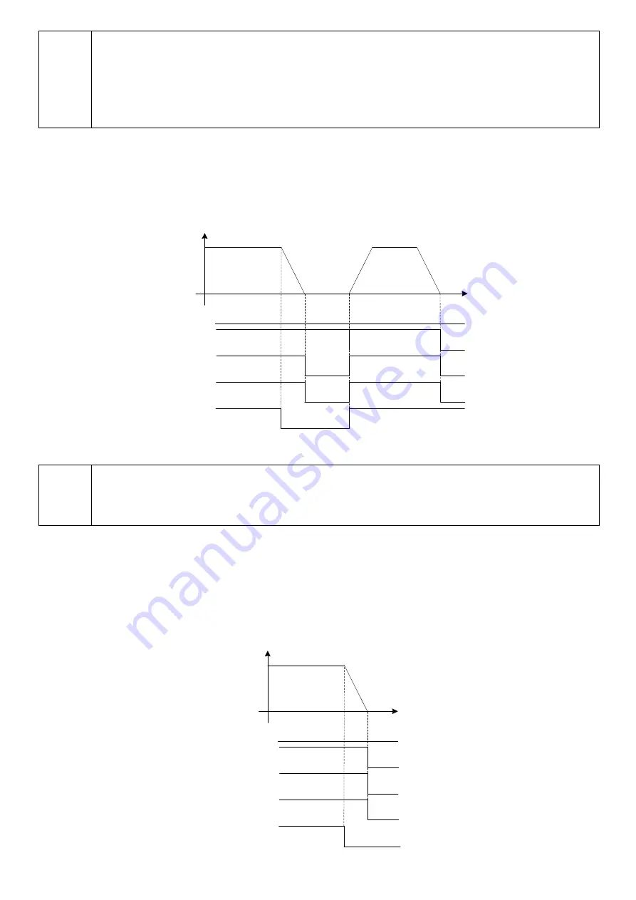
(4) Pause
If the pause signal is turned on during homing, interrupt positioning, positioning data operation or immediate
value data operation, operation is interrupted and the motor is stopped while the signals remains turned on.
After the signal is turned off, the operation continues. In-position [INP] is not turned on in a pause.
Speed
[RDY]
Zero deviation
Zero speed
[INP]
Time
Pause
OFF
OFF
ON
ON
OFF
ON
OFF
ON
ON
ON
OFF
OFF
ON
Note
(1)Acceleration/ deceleration follow the settings of parameters P1.37 through 40 and the state of
input signal ACC0, or the settings of acceleration/deceleration time data.
(2)The in-position [INP] signal shown in the figure indicates the state in the level output mode.
(5) Positioning cancel
If the positioning cancel signal is turned on during motor rotation, operation is stopped and controlled stop is
caused according to the deceleration time setting. While the positioning cancel signal remains active,homing,
interrupt positioning, positioning data operation or immediate value data operation does not start.
The signal is enabled for speed operation and pulse operation.
Speed
[RDY]
[INP]
Time
Positioning
cancel
ON
OFF
OFF
ON
ON
OFF
ON
OFF
ON
Zero deviation
Zero speed


