SATELLINE-EASy Pro 35W
User Guide v.1.4
78
S ADD
DATA
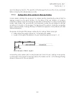
- The above is the same message after being relayed from the last repeater in the chain (repeater
2) to the substation.
DATA
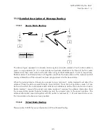
- The above is the same message being relayed via the serial interface of the substation radio
modem to the terminal device.
In a situation where the substation transmits data towards the base-station the address is formed
in a similar way, but the order of the addresses is reversed:
R2 ADD R1 ADD M ADD
DATA
-In the above, R2 ADD is address of repeater 2, R1 ADD is address of repeater 1 and M ADD is
the address of the base-station.
10.3.2
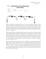
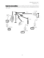
Repeater chain using address pairs
In a situation where the terminal devices and substations cannot form address fields, but are able
to recognise messages addressed to them, alternating address pairs may be used. Transmit
address (TX) and receive address (RX) alternate in the order shown in the table below.
Address type
Base-station address
Repeater 1 and the
addresses of the
substations of the base-
station
Repeater 1
substations
addresses
TX-address
Address 1
Address 2
Address 1
RX-address
Address 2
Address 1
Address 2
In a network where alternating addresses are utilised, the exact route that is used to relay a
message to a certain radio modem is fixed at the time of installation and configuring the system.
The order of the addresses must be the same as the order of the route that is used to relay the
message to the said radio modem. It should be noted however, that in network where alternating
addresses are used the base-station and substations will hear their own messages repeated.


