BG0491 REV. A12
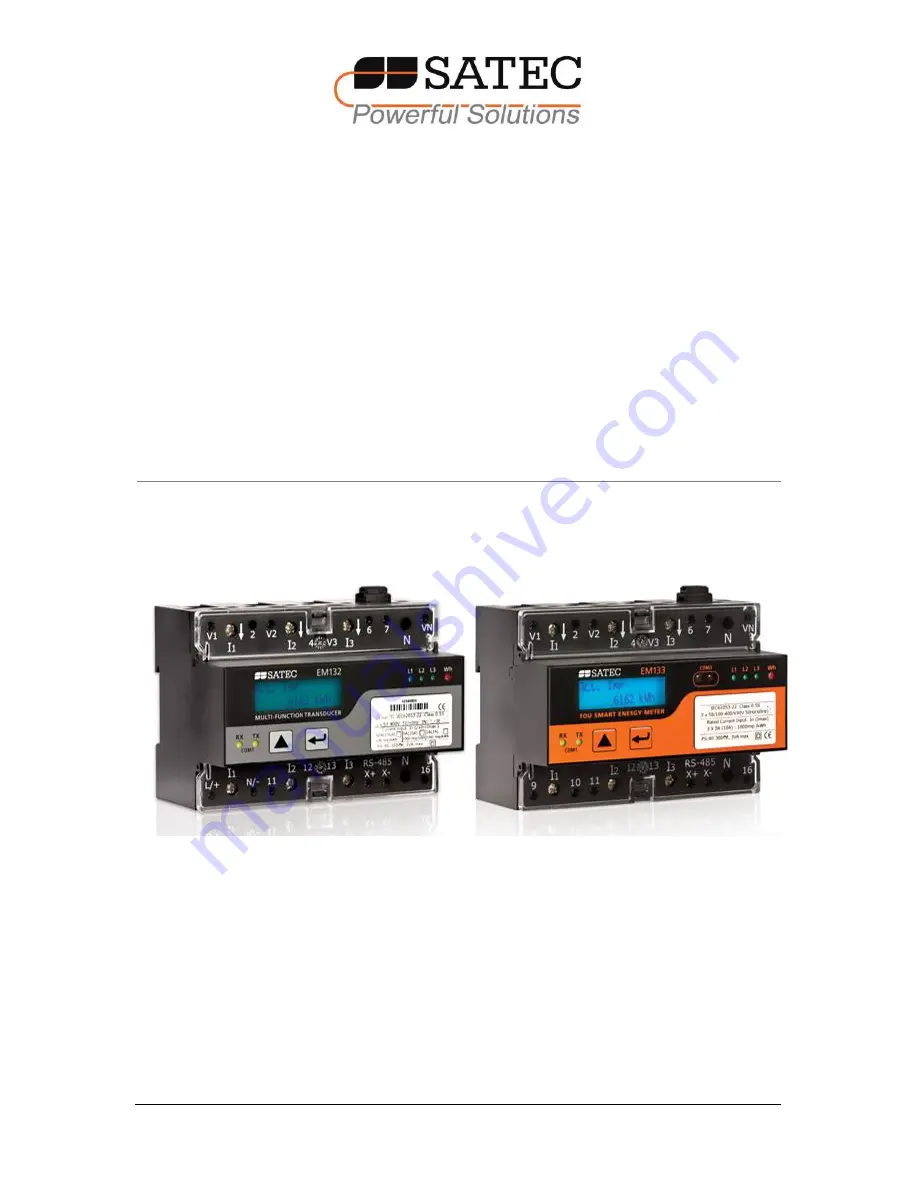
EM13x Series
SMART MULTIFUNCTION METER
Installation and Operation Manual
Page 1: ...BG0491 REV A12 EM13x Series SMART MULTIFUNCTION METER Installation and Operation Manual ...
Page 2: ...uly authorized representative of the manufacturer may open your instrument The unit should only be opened in a fully anti static environment Failure to do so may damage the electronic components and will void the warranty The greatest care has been taken to manufacture and calibrate your instrument However these instructions do not cover all possible contingencies that may arise during installatio...
Page 3: ...trument to rain or moisture 5 The secondary of an external current transformer must never be allowed to be open circuit when the primary is energized An open circuit can cause high voltages possibly resulting in equipment damage fire and even serious or fatal injury Ensure that the current transformer wiring is secured using an external strain relief to reduce mechanical strain on the screw termin...
Page 4: ... of the meter hazardous voltages are present in the input terminals Failure to observe precautions can result in serious or even fatal injury or damage to equipment For complete and accurate in depth instructions refer to the following chapters in this manual Installing the EM13X SERIES Mounting the EM13X SERIES Unit To mount the EM13X SERIES on Din rail Hang the EM13X Series unit on the DIN Rail ...
Page 5: ...CT wires through the meter CT terminals Observe the arrow that indicates the current direction In case of a retrofit application or high current external SATEC CT or Split Core where each external CT ends with two wires Connect the wire to the meter current termination screws Connect the measured voltage inputs Connect COM1 RS 485 communication port In case of EM132 133 model with Aux Power supply...
Page 6: ...6 EM13x Series SMART MULTIFUNCTION METER CT wiring To connect an Option module Assemble the module on the meter Power the EM13X Series unit on Assembly a small module ...
Page 7: ...all the PAS application software on your PC Configure the PAS database for your meter Configure the PAS communications settings Upgrade the meter firmware if a new version is available Set up the meter using the PAS application software Configure your security settings through the meter security setup Configure your communication protocol settings Configure Billing TOU registers At this stage the ...
Page 8: ...Connecting the wires 25 Typical Installation 26 Terminals 31 Power Source Connection 32 Voltage Input connection 34 Current Input Connection 35 Wiring Diagrams 36 2 5 Battery Replacement 43 2 6 I O Connections 44 2DI 1RO Standard 44 4DI 2RO Module 45 8 DI module 46 12DI 4RO Module 46 4AO Module Analog Outputs 47 2 7 Communications Connections 49 RS 485 Connection 50 ETH module COM2 Ethernet Connec...
Page 9: ...ng Up Serial Communication Ports 74 Setting up the Ethernet 76 Setting up GPRS Network 77 Setting Up eXpertPower Client 78 Setting Up TCP Notification Client 79 5 2 General Meter Setup 80 Basic Meter Setup 80 Device Options 83 Configuring Digital Inputs 84 Configuring Relay Outputs 86 Configuring Analog Outputs 89 Configuring Counters 91 Configuring Alarm Control Setpoints 93 Configuring the Displ...
Page 10: ...Scheduler 132 8 3 Viewing Files On line 134 8 4 Exporting Files 134 Exporting Files in COMTRADE and PQDIF Formats 134 Exporting Files in Excel Format 135 8 5 Archiving Files 136 Chapter 9 Viewing Files 137 9 1 Operations with Files 137 9 2 Viewing Options 137 Customizing Views 137 Working with Tables 138 Working with Graphic Windows 138 9 3 Viewing the Event Log 140 9 4 Viewing the Data Log 141 Ap...
Page 11: ...t inputs In 5A Imax 10A EM132 EM133 1 internal CT transformer operated configuration with current inputs In 1A Imax 2A EM132 EM133 RS5 external CT transformer operated configuration with current inputs secondary current In 2 mA Imax 5mA EM132 EM133 50 internal CT direct connection configuration with current inputs In 50A Imax 63A EM132 EM133 HACS external CT direct connection configuration with cu...
Page 12: ...with current inputs In 50A Imax 63A EM132 EM133 21DC HACS external CT direct connection configuration with current inputs secondary current In 20mA Imax 40mA All models series include the following units 2 lines of 16 characters LCD display A standard RS 485 communication port Infra Red Communication port and an additional optional Ethernet Profibus or RS 232 RS 422 RS 485 or RF Modem port These p...
Page 13: ...e tariff calendar schedule Automatic daily energy and maximum demand profile log for total and tariff registers Voltage and current THD current TDD and K Factor up to 40th order harmonic Voltage and current harmonic spectrum and angles Real time Waveform Capture Real time scope mode waveform monitoring capability Simultaneous 6 channel one cycle waveform capture at a rate of 64 samples per cycle P...
Page 14: ...unication protocols eXpertPower client for communicating with the SATEC proprietary eXpertPower Internet services with the Ethernet GPRS module TCP notification client for communicating with a remote MODBUS TCP server on events or periodically on a time basis with the Ethernet GPRS module Meter Security Password security for protecting meter setups and accumulated data from unauthorized changes Up...
Page 15: ...itoring external contacts and receiving pulses from energy water and gas meters Programmable de bounce time 1 ms scan time 4 electro mechanical relay outputs RO for alarms and controls and for output energy pulses unlatched latched and pulse operations failsafe operation for alarm notifications programmable pulse width direct remote relay control through communications 1 cycle update time Analog O...
Page 16: ...can be customized to best suit the user application Device Resolution A low or high resolution option can be selected for the presentation of voltage current and power for use in high and low power applications Display Options Different display options are available for customization to be used in dark or non safe locations or in places that are hardly accessible for observation ...
Page 17: ...Current per phase kW per phase kvar per phase kVA per phase Power Factor per phase Total kW Total kvar Total kVA Total Power Factor Frequency Neutral Current Voltage Current unbalance Amps Volt Demands Ampere Volt Demand per phase Ampere Maximum Demand per phase Voltage Maximum Demand per phase Power Demands kW Accumulated Demand Import Export kvar Accumulated Demand Import Export kVA Accumulated ...
Page 18: ...asons x 4 types of day Harmonic MeasurementsEH Voltage THD per phase Current THD per phase Current TDD per phase K factor per phase Voltage harmonics per phase up to order 40 Current harmonics per phase up to order 40 Voltage harmonic angles up to order 40 Current harmonic angles up to order 40 Fundamental Component Voltage and Current per phase kW PF per phase kvar KVA per phase Total kW PF Total...
Page 19: ...Chapter 1 General Information Labelling EM13x Series SMART MULTIFUNCTION METER 19 1 5 Labelling Figure 1 1 EM133 label UL marking Figure 1 2 EM133 label NMI marking Figure 1 3 EM133 label CE MID marking ...
Page 20: ...nmental conditions as specified in Technical Specifications in Appendix A Electrical requirements as specified in Technical Specifications in Appendix A See Technical Specifications in Appendix A for more details 2 2 Package Contents The EM13X Series SMART MULTIFUNCTION METER package contains the following items EM13X Series SMART MULTIFUNCTION METER unit Technical Documentation CD EM13X Series Qu...
Page 21: ... Chapter 2 Installation Mechanical Installation EM13x Series SMART MULTIFUNCTION METER 21 Figure 2 1 Dimensions ...
Page 22: ...lation 22 EM13x Series SMART MULTIFUNCTION METER Wall Mounting To mount the meter on the wall Position the meter on the wall according to hole locations as shown in figure 2 2 Affix the meter using washers and nuts Figure 2 2 Surface Mounting ...
Page 23: ...llation Mechanical Installation EM13x Series SMART MULTIFUNCTION METER 23 DIN Rail Mounting The EM13X Series can be mounted on a standard 35 mm DIN rail as shown in figure 2 3 Figure 2 3 EM13X Series DIN Rail Mounting ...
Page 24: ...ut OFF Failure to observe this practice can result in serious or even fatal injury and damage to equipment Turn off the EM13X Series auxiliary power supply or voltage supply inputs SE model Remove the module connector cover from the EM13X Series to access the module connector as shown in figure 2 4below Figure 2 4 EM13X Series module connector location Figure 2 5 EM13X Series module assembly ...
Page 25: ...opriate for the application SATEC requires using crimped ferrules on stranded wire Table 3 below summarizes the different conductors sizes to be used in the EM133 external connections Table2 WiringConfigurations Terminals Conductor size Torque Nm Notes EM133 model Minimum AWG mm Maximum AWG mm Aux Power Supply Inputs L N N A in EM133 SE models 22 0 5 12 4 0 0 5 0 7 Use 600V insulated conductors Re...
Page 26: ... Chapter 2 Installation Electrical Installation 26 EM13x Series SMART MULTIFUNCTION METER Typical Installation Figure 2 6a Typical Installation Diagram with Auxiliary Power Supply ...
Page 27: ...gram with Self Energized Power Supply direct connection with HACS 1 SATEC RF chokes to be installed between CBR and Meter Voltage Inputs in residential area or other places require ANCI C12 20 compliance Otherwise it may be bypassed 2 AC0242 shall be routed with the voltage lines bundled separately from communication I O lines ...
Page 28: ... Chapter 2 Installation Electrical Installation 28 EM13x Series SMART MULTIFUNCTION METER Figure 2 6c Typical Installation Diagram with Self Energized Power Supply direct connection ...
Page 29: ...th Self Energized Power Supply Transformer Operated indirect connection 1 SATEC RF chokes to be installed between CBR and Meter Voltage Inputs in residential area or other places require ANCI C12 20 compliance Otherwise it may be bypassed 2 AC0242 shall be routed with the voltage lines bundled separately from communication I O lines ...
Page 30: ... Chapter 2 Installation Electrical Installation 30 EM13x Series SMART MULTIFUNCTION METER Figure 2 6e Typical Installation Diagram with 12 24 VDC Auxiliary Power Supply ...
Page 31: ...ilt in part of the meter equipment The terminals are divided in two different terminal categories 1 High power terminal dedicated to current terminals only with a torque rating of 2 0 2 3Nm 2 Low power terminal dedicated to voltage Digital Inputs COM1 and Relay output terminals only with a torque rating of 0 5 0 7Nm Figure 2 7a Terminals View EM133 Model ...
Page 32: ...d Before installing ensure that all incoming power sources are shut OFF Failure to observe this practice can result in serious or even fatal injury and damage to equipment e The current sensors may not be installed in a panel where they exceed 75 of the wiring space of any cross sectional area within the panel The power source can be a dedicated fuse or a monitored voltage if it is within the inst...
Page 33: ... Chapter 2 Installation Electrical Installation EM13x Series SMART MULTIFUNCTION METER 33 Figure 2 8 EM13X Series Auxiliary Power Supply connection ...
Page 34: ...ut OFF Failure to observe this practice can result in serious or even fatal injury and damage to equipment e The current sensors may not be installed in a panel where they exceed 75 of the wiring space of any cross sectional area within the panel EM13x Series with Aux Power Supply 690V Inputs Standard Figure 2 9EM13X Series with Aux Power Supply measured Voltage connections 690V inputs are usually...
Page 35: ...current 2A maximum using internal CT transformer operated Connection 5A nominal current 10A maximum using internal CT transformer operated Connection 50A nominal current 63A maximum using internal CT Direct Connection in EM133 SE model Current Inputs and Voltage Inputs are internally connected together 20mA nominal current 40mA maximum using HACS external CT provided by SATEC Transformer Connectio...
Page 36: ...t Delta direct connection using 2 CTs 3dir2 2 12 4 wire 3 element Wye direct connection using 3 CTs 4Ln3 or 4LL3 2 13 4 wire 3 element Wye connection using 3 PTs 3 CTs 4Ln3 or 4LL3 2 14 3 wire 2 element Open Delta connection using 2 PTs 2 CTs 3OP2 2 15 4 wire 2 element Wye connection using 2 PTs 3 CTs 3Ln3 or 3LL3 2 16 3 wire 2 element Open Delta connection using 2 PTs 3 CTs 3OP3 2 17 4 wire 3 ele...
Page 37: ... Chapter 2 Installation Electrical Installation EM13x Series SMART MULTIFUNCTION METER 37 Figure 2 12 3 Wire 2 Element Delta Direct Connection Using 2 CTs Wiring Mode 3dir2 ...
Page 38: ... Chapter 2 Installation Electrical Installation 38 EM13x Series SMART MULTIFUNCTION METER Figure 2 13 4 Wire Wye 3 Element Direct Connection Using 3 CTs Wiring Mode 4LL3 or 4Ln3 ...
Page 39: ...cal Installation EM13x Series SMART MULTIFUNCTION METER 39 Figure 2 14 4 Wire Wye 3 Element Connection Using 3 PTs 3 CTs Wiring Mode 4LL3 or 4Ln3 Figure 2 15a 3 Wire 2 Element Open Delta Connection Using 2 PTs 2 CTs Wiring Mode 3OP2 ...
Page 40: ...UNCTION METER Figure 2 15b 3 Wire 2 Element Open Delta Connection Using 3 PTs 2 CTs Wiring Mode 3OP2 This configuration provides accurate power measurements only if the voltages are balanced Figure 2 16 4 Wire Wye 2 Element Connection Using 2 PTs 3 CTs Wiring Mode 3LL3 or 3Ln3 ...
Page 41: ...al Installation EM13x Series SMART MULTIFUNCTION METER 41 Figure 2 17 3 Wire 2 Element Open Delta Connection Using 2 PTs 3 CTs Wiring Mode 3OP3 Figure 2 18 4 Wire 3 Element Delta Direct Connection Using 3 CTs Wiring Mode 4LL3 or 4Ln3 ...
Page 42: ... Chapter 2 Installation Electrical Installation 42 EM13x Series SMART MULTIFUNCTION METER Figure 2 19 3 Wire 2 Element Broken Delta Connection Using 2 PTs 3 CTs Wiring Mode 3bLn3 or 3bLL3 ...
Page 43: ...nt The battery replacement must be performed while equipment power supply is ON To replace the CR2032 RTC battery 1 Remove the EM13X Series cover 2 Remove the old battery by lifting up the battery holder retractable tab 3 Place the new CR2032 battery into the battery holder while holding up the battery holder retractable tab in such a way that the battery pole is toward the battery holder as shown...
Page 44: ...mage to equipment For I O ratings see Technical Specifications in Appendix A 2DI 1RO Standard Relay Output The EM13X Series basic provides one dry contact relay SSR FORM A for energy pulsing alarms or remote control Figure 2 8 EM13X Series Relay output connection Digital Inputs Two optically isolated status inputs are provided for status monitoring pulse counting external power demand period and t...
Page 45: ...in serious or even fatal injury and damage to equipment Figure 2 10 4DI 2RO Module Assembly Relay Outputs There are two relay outputs provided for energy pulsing alarms or remote control Figure 2 11 Relay Output Connection Digital Inputs Four optically isolated status inputs are provided for status monitoring pulse counting external power demand period and time synchronization Figure 2 12 4 DI 2DO...
Page 46: ...ng pulse counting external power demand period and time synchronization Figure 2 13 8 DI Digital Input Connection 12DI 4RO Module The 12DI 4RO module can be equipped with optional communication port COM2 ETHERNET or RS 422 485 Figure 2 14 12DI 4RO Module Relay Outputs There are four electro mechanic relay outputs provided for energy pulsing alarms or remote control ...
Page 47: ...atus monitoring pulse counting external power demand period and time synchronization Figure 2 16 12 Digital Input Connection 4AO Module Analog Outputs The 4AO module has four optically isolated analog outputs with an internal power supply and current output options of 0 20 mA and 4 20 mA current loop load of up to 500 Ohm 0 1 mA and 1 mA 2mA 100 overload current loop load of up to 5 kOhm ...
Page 48: ... which has no live parts which are ACCESSIBLE The RATING of the insulation of the external equipment for use with the 4AO module shall comply according to Installation Category III for insulation to be suitable for SINGLE FAULT CONDITION The external equipment TERMINAL connection type is normally terminal block for wire size 14 AWG up to 1 5 mm2 The type of equipment that might be connected to the...
Page 49: ...Failure to observe this practice can result in serious or even fatal injury and damage to equipment Several communication options are available for the EM13X Series COM1 standard RS 485 COM2 optional module Ethernet 10 100BaseT PROFIBUS DP CANopen RS 232 or RS 422 485 GPRS 3G 4G RF COM3 standard IR A full description of the communication protocols is found in the EM13X Series protocol guides that ...
Page 50: ...unications Connections 50 EM13x Series SMART MULTIFUNCTION METER RS 485 Connection Figure 2 19 COM1 RS 485 2 Wire Connection Communication cable Specification Shielded 22AWG Note pay attention to GND connection SH GND RS 485 COM1 ...
Page 51: ...hich has no live parts which are ACCESSIBLE The RATING of the insulation of the external equipment for use with the ETH module shall comply according to Installation Category III for insulation to be suitable for SINGLE FAULT CONDITION The external equipment TERMINAL connection type is RJ 45 The type of equipment that might be connected to the TERMINAL is Personal Computer PC or LAPTOP 10 100Base ...
Page 52: ...quipment which has no live parts which are ACCESSIBLE The RATING of the insulation of the external equipment for use with the PRO module shall comply according to Installation Category III for insulation to be suitable for SINGLE FAULT CONDITION The external equipment TERMINAL connection type is DB9 The type of equipment that might be connected to the TERMINAL is Programmable Logic Controller for ...
Page 53: ...Chapter 2 Installation Communications Connections EM13x Series SMART MULTIFUNCTION METER 53 CANopen module COM2 CANopen Connection RS 232 422 485 module COM2 Connection Figure 2 22 COM2 RS 232 connection ...
Page 54: ...allation Category III for insulation to be suitable for SINGLE FAULT CONDITION The external equipment TERMINAL connection type is normally terminal block for wire size 14 AWG up to 1 5 mm RS 422 485 port and DB9 male to female cable more than 22 AWG 0 3mm The type of equipment that might be connected to the TERMINAL is Personal Computer PC or LAPTOP Connecting a GSM GPRS 3G module A GSM GPRS modem...
Page 55: ...ennas internal Antenna for installation into plastic closet or no metallic environment For metallic installation use external antenna See Setting Up GPRS in Chapter 5 for information on configuring GPRS communications in your meter Connecting an RF module Figure 2 25 COM2 RF module Connection The RF modem module can be equipped with two different antennas internal Antenna for installation into pla...
Page 56: ...e enabled through the Device Options setup When in test mode the energy and demand accumulators do not account for consumed energy COMPort Activity LEDs The meter has two yellow LEDs RX and TX which indicate activity on the COM1 communication port The LEDs flash when the port is receiving or transmitting data VOLTAGES LEDs The meter has three green LEDs L1 L2 and L3 which indicate voltage measurem...
Page 57: ...r 1 to 2 seconds Extended press or press and hold for 5 seconds or longer The function of each button changes depending on what operating mode the display is in The SCROLL button operates once it is briefly pressed It has two functions In data display mode it scrolls through the display pages In programming mode it scrolls through the menu items and allows changing a selected digit when entering n...
Page 58: ...inuous operation if you need to work in dark for more time Auto Return If the Auto Return feature is enabled and no button is pressed for the programmable Auto Return interval 1 to 30 minutes for data displays fixed at 5 minutes for setup menus the display automatically returns to the default page from any other data display or a setup menu If the Auto Scroll feature is enabled the display immedia...
Page 59: ... billing period data 3 Energy Total and Phase Energy data 4 MAX DEMAND Engineering maximum demands 5 Measurement Instrumentation data 6 Phase Rotation Phase I O and Counter data 7 Diagnostics Device diagnostics messages and Device service data TEST Mode Data Display The TEST data display is shown in TEST mode in place of the billing period data displays NORM is replaced by TEST See Device Options ...
Page 60: ...nd Reg2 for TOU reactive energy are predefined TOU Register factory setup can be changed by user see Configuring Billing Tariff Registers and Configuring the Daily Tariff Schedule in Chapter 5 Reg 1 T1 Imp 517 kWh Tariff 1 Import Active energy data Reg 1 T2 Imp 114 kWh Tariff 2 Import Active energy data Reg 1 T3 Imp 94 kWh Tariff 3 Import Active energy data Reg 2 Imp 221 kvarh Total Import Reactiv...
Page 61: ...gy data Total Import Phase 3 active energy data Tariff 1 Import Phase 3 active energy data Tariff 2 Import Phase 3 active energy data Tariff 3 Import Phase 3 active energy data TOU Maximum Demand Power Data Display The following example demonstrates the TOU Maximum Demand displays for three configured registers MAX kW imported MAX kvar imported and MAX kVA imported and for three active tariff rate...
Page 62: ... Imp MAX 0 008 kW Tariff 2 Import max active power dmd data Reg 1 T3 Imp MAX 0 002 kW Tariff 3 Import max active power dmd data Reg 2 Imp MAX 0 003 kvar Total Import Max DMD reactive power data Reg 2 T1 Imp MAX 0 003 kvar Tariff 1 Import max reactive power dmd data Reg 2 T2 Imp MAX 0 003 kvar Tariff 2 Import max reactive power dmd data Reg 2 T3 Imp MAX 0 001 kvar Tariff 3 Import max reactive power...
Page 63: ...x DMD active power data MAX DMD P Exp 0 kW Total Export Max DMD active power data MAX DMD Q Imp 0 003 kvar Total Import Max DMD reactive power data MAX DMD Q Exp 0 kvar Total Export Max DMD reactive power data MAX DMD S 0 008 kVA Total Import Max DMD apparent power data MAX DMD I1 0 A Max DMD Phase 1 current data MAX DMD I2 0 A Max DMD Phase 2 current data MAX DMD I3 0 A Max DMD Phase 3 current da...
Page 64: ... order of phases when connecting wires to the meter terminals DISPLAY Description V1 0 V V2 0 V V1 and V2 Phase to neutral voltages Only displayed in 4 wire configurations with a neutral V3 0 V V2 Phase to neutral voltage V12 0 V V23 0 V Phase to Phase voltages V31 0 V Phase to Phase voltages I1 0 A I2 0 A Phase currents I3 0 A In 0 A Phase currents neutral current is calculated P 0 kW Q 0 kvar To...
Page 65: ...L3 PF 0 Phase 3 apparent power and power factor H1 P 0 kW H1 Q 0 kvar First Harmonic Total powers H1 S 0 kVA H1 PF 0 First Harmonic Total apparent power and total power factor H1 L1 0 kW H1 L1 0 kvar First Harmonic Phase 1 active and reactive power H1 L1 0 kVA H1 L1 0 PF First Harmonic Phase 1 apparent power and power factor H1 L2 0 kW H1 L2 0 kvar First Harmonic Phase 2 active and reactive power ...
Page 66: ...HD V3 THD 0 I3 THD 0 Phase 3 voltage and current THD I1 TDD 0 I2 TDD 0 Total Demand current Distortion I3 TDD 0 Total Demand current Distortion V Unb 0 I Unb 0 Voltage and Current unbalance Freq 0 Hz Frequency V1 Ang 0 I1 Ang 0 Voltage and Current Phase 1 angles relative to V1 voltage V2 Ang 0 I2 Ang 0 Voltage and Current Phase 2 angles relative to V1 voltage V3 Ang 0 I3 Ang 0 Voltage and Current ...
Page 67: ...or meter identification and inspection like product and firmware information communication settings and so on and shows device diagnostic messages recorded as a result of the meter self test diagnostics during start up and operation If there are diagnostic messages Some of the diagnostics events are cleared automatically as the event source disappears See Device Diagnostic Codes in Appendix G for ...
Page 68: ...n S N 12345744 S W V12 1 1 Meter identification info serial number and device SW version Boot V1 1 1 Modem N A Boot SW version and Modem setup COM1 a221 b115 2 Modbus RTU Communication port COM1 info COM2 RF a221 Modbus RTU Communication port COM2 info COM3 a1 b19 2 Modbus RTU Communication port COM3 info ...
Page 69: ...ew setting To reject your changes and restore the previous value use a short press on the SELECT ENTER button to return to the higher level window Password Security The setup menus are secured by 8 digit user passwords Every time you enter programming mode you are prompted for a correct password The meter is primarily shipped with all passwords preset to 9 at the factory It is recommended that you...
Page 70: ...ice setup Low High Options Device options setup Low High COM1 COM1 serial port setup Low Medium COM2 COM2 serial port setup Low Medium COM3 COM3 serial port setup Low Medium Local Local settings Low Medium Disp Display setup Low Low Access Meter passwords setup High High Loader Launches flash download via a local serial port Medium Medium Access to the RESET menu entries is allowed depending on yo...
Page 71: ... a list of values use the SCROLL button to scroll through the list until a desired value appears in the window It an option is represented by a numeric value use the SCROLL button to adjust each digit to the desired value and use a short press on the SELECT ENTER button to move through digits Once the desired value is selected press the SELECT ENTER button for more than 1 second to save your new s...
Page 72: ...puter on your Desktop Click on your CD drive icon select the PAS directory and then double click on Setup shown as an Application type file Follow InstallShield Wizard instructions on the screen PAS is installed by default to the C Pas folder When installation is complete the PAS icon appears on your Desktop Double click on the PAS icon to run PAS For general information on how to work with PAS se...
Page 73: ... Sites directory Type a site name for your device in the File name box click New and then click OK On the Instrument Setup tab select EM13X Series in the Model box PAS automatically selects the appropriate instrument options for your meter Select a correct CT secondary current 5A or 1A for your meter If you wish to add any comments for your meter type the comments in the Comment box For more devic...
Page 74: ...ase for your device as shown in Chapter 4 5 1 Configuring Communications Setting Up Serial Communication Ports Using the Front Display Select COM1 through COM3 from the main menu See Viewing and Changing Setup Options in Chapter 3 for information on navigating in menus See the table below for available communication options Using PAS Select Communications Setup from the Meter Setup menu and then c...
Page 75: ...ically detected by the meter Address Device address MODBUS 1 247 DNP3 0 65532 IEC 60870 5 1 4095 1 Device network address Baud Rate Baud rate COM1 300 115 2 kbps COM2 300 115 2 kbps COM3 9600 38400 kbps 19 2 kbps The port baud rate Data Parity Data format and parity 7E 8N 8E 8N 7E data format should not be used with the MODBUS RTU and DNP3 protocols Send Delay Response delay 0 1000 ms 5 ms The min...
Page 76: ...er Default IP Address Device IP Address 192 168 0 203 Subnet Mask Network Subnet Mask 255 255 255 0 Def Gateway Network Default Gateway 192 168 0 1 TCPServicePort 502 Modbus TCP 20000 DNP3 TCP 502 NOTES The meter provides the permanent MODBUS TCP server on port 502 Selecting the DNP3 TCP service port launches the second DNP3 TCP server allowing simultaneous connections on both TCP ports Selecting ...
Page 77: ... The EM13X Series can provide wireless GPRS communications with the remote Modbus TCP server via an external Enfora GSM1308 SA G GSM GPRS modem See Connecting a GSM GPRS modem in Chapter 2 on how to connect a modem to your meter Using PAS Select Communications Setup from the Meter Setup menu and then click on the GPRS Setup tab Select Communications Setup from the Meter Setup menu and then click o...
Page 78: ... setup see Setting Up Serial Communication Ports Configure your eXpertPower client see Setting Up eXpertPower Client or and TCP Notification client see Setting Up TCP Notification Client for communicating with a remote server You can check the status of the GPRS communications from the front panel via the Status Display or via the Device Control dialog in PAS see Viewing Communication Status and S...
Page 79: ... Time to Next Session min 1 99999 The time remaining to the next connection session NOTES Do not enable the eXpertPower client in your meter if you do not use the eXpertPowerTM service Do not change the connection time setting It is for information only The eXpertPower server updates it automatically Setting Up TCP Notification Client The TCP notification client can establish connections with a re...
Page 80: ...oint to respond to desired triggers or to periodic time events and put the Notification action to the setpoint action list see Configuring Alarm Control Setpoints See the PM130 PLUS Modbus Reference guide for more information on operation of the notification client and the notification message structure 5 2 General Meter Setup Basic Meter Setup This section describes how to configure the EM13X Ser...
Page 81: ...and period 1 2 3 5 10 15 20 30 60 min E external sync 15 min The length of the demand period for power demand calculations If the external synchronization is selected a pulse front on the digital input DI1 denotes the start of the demand interval Num Per The number of blocks in the sliding demand window 1 15 1 The number of blocks to be averaged for sliding window demands ADmdPer Volt Ampere Deman...
Page 82: ...CTs 2 element 4LL3 4 wire Wye using 3 PTs 3 element line to line voltage readings 3OP3 3 wire Open Delta using 3 CTs 2 element 3LN3 4 wire Wye using 2 PTs 2 element line to neutral voltage readings 3LL3 4 wire Wye using 2 PTs 2 element line to line voltage readings 3BLN3 3 wire Broken Delta using 2 PTs 3 CTs 2 element line to neutral voltage readings 3BLL3 3 wire Broken Delta using 2 PTs 3 CTs 2 e...
Page 83: ...d Setting this option puts the meter into the energy test mode see Energy Pulse LED in Chapter 3 PowMode Power Calculation Mode Reactive using reactive power S f P Q NonActive using non active power Q f S P S f P Q The method used for calculating reactive and apparent powers see Power Calculation Modes below EngyRoll Energy Roll Value 10000 10000 kWh 100000 100000 kWh 1000000 1000000 kWh 10000000 ...
Page 84: ...olts and THD 10 for currents In networks with high harmonics the second method is preferable When the non active power calculation mode is selected active power is measured directly apparent power is taken as product S V x I where V and I are the RMS volts and amps and reactive power called non active power is calculated as 2 2 P S N Configuring Digital Inputs The EM13X Series can be provided with...
Page 85: ...r Setup EM13x Series SMART MULTIFUNCTION METER 85 Using PAS Select General Setup from the Meter Setup menu and then click on the Digital Inputs tab Figure 5 8 General Setup Dialog Box Digital Inputs Dialog Box The available options are shown in Table 11 ...
Page 86: ...n the Relay Outputs tab Parameter Options Default Description Input Polarity NORMAL INVERTING NORMAL For the normal polarity the open to closed transition is considered closed For the inverting polarity the closed to open transition is considered a closed Pulse Input Mode PULSE MODE KYZ MODE PULSE MODE In pulse mode either leading or trailing edge of the input pulse is recognized as an event In KY...
Page 87: ... Chapter 5 Configuring the EM13X Series General Meter Setup EM13x Series SMART MULTIFUNCTION METER 87 Figure 5 9 General Setup Dialog Box Relay Outputs Tab ...
Page 88: ... non active state KYZ mode transition pulse the relay generates transition pulses The relay changes its output state upon each command and remains in this state until the next command Polarity NORMAL N O INVERTING N C NORMAL Normal polarity the relay is normally de energized in its non active state and is energized in its active operated state Inverting polarity the relay is normally energized in ...
Page 89: ...rity active pulse edge for energy pulses and a pulse width Select a source energy accumulator and the pulse rate for your output Send your new setup to the meter Configuring Analog Outputs The meter can be ordered with four optional analog outputs with options for 0 1mA 1mA 0 20mA and 4 20mA current outputs Using PAS Select General Setup from the Meter Setup menu and then click on the Analog Outpu...
Page 90: ...on on an analog output Scaling Non Directional Analog Outputs For non directional analog outputs with a 0 1mA 0 20mA or 4 20mA current option you can change both zero and full engineering scales for any parameter The engineering scale need not be symmetrical Scaling Directional Power Factor The engineering scale for the signed power factor emulates analog power factor meters The power factor scale...
Page 91: ... 2 mA set the analog output scales as follows 0 2 mA set the 1 mA scale to of the required full scale output for uni directional parameters and set the 0 mA scale to the negative full scale and the 1 mA scale to zero for bi directional parameters 2 mA set the 1 mA scale to of the required full scale output for both uni directional and bi directional parameters For example to provide the 0 to 2 mA ...
Page 92: ... DI4 DI5 DI6 DI7 DI14 None Links a digital input to the counter Multiplier 1 9999 1 The value added to the counter when a pulse is detected on the pulse source input Counter Value Displays the present counter contents You can preset a counter to a required value or clear it without affecting the counter setup To preset or clear a counter Click the Online button on the PAS toolbar before accessing ...
Page 93: ...that produce a required action The meter provides 16 control setpoints with programmable operate and release delays Each setpoint evaluates a logical expression with one trigger argument Whenever an expression is evaluated as true the setpoint performs a programmable action that can send a command to the output relay or increment a counter The logical controller provides very fast response to even...
Page 94: ...it defines the release threshold for the trigger The trigger thresholds are specified in primary units If you do not want to use hysteresis for the trigger set the Release Limit to the same value as the Operate Limit Using Binary Triggers Binary digital triggers like digital inputs and relays are tested for ON CLOSED or OFF OPEN status In the PM130 the binary events are level sensitive events An e...
Page 95: ...s that are shared for each target relay between all setpoints using an OR scheme A relay output is operated when one of the setpoints linked to the relay is activated and remains operated until all of these setpoints are released except for latched relays that require a separate release command to be deactivated Using Time Counters Any of the general counters can be used to count the setpoint oper...
Page 96: ...ons Display Label Parameter Options Default Description AutuoScroll Display update rate Disabled 2 30sec 5 sec Defines the interval between display updates AutoReturn Auto return to the main screen Disabled 1 30 mn 5 mn Enables automatic return to the main display if no buttons are pressed for 5 minutes Backlight Display Backlight period Continuous 1 10 mn 1 Defines the display backlight light on ...
Page 97: ...Setup menu and then click on the Display Setup tab Figure 5 13 General Setup Dialog Box Display Setup Tab The available options are listed in the table 17 below See Display Operations in Chapter 3 for more information on display functionality and configuring display options See Data Displays for information on display page contents and enumeration ...
Page 98: ...sabled 1 5 10 15 20 25 30 min 5 Defines the time delay before returning to the default page Backlight Backlight Time Continuous 1 10 min 1 Defines the time while the backlight is ON Phase Power Phase powers display mode Enabled Disabled Disabled Disables or enables phase powers in the main display Fundamental Power Fundamental component display mode Enabled Disabled Disabled Disables or enables fu...
Page 99: ...ST is disabled the RTC operates in standard time only When enabled the meter automatically updates the time at the pre defined DST switch dates Start Mon DST Start Month January to December March The month when Daylight Saving Time begins Start Week DST Start Week 1st to 4th and last Second The 2nd week of the month when Daylight Saving Time begins Start Day DST Start Day The weekday Sunday The 2n...
Page 100: ... points are preset for the U S A The daylight saving time option is disabled in the PM130 by default If the daylight saving time option is disabled you need to manually adjust the device clock for daylight saving time Time Synchronization Pulses External time synchronization pulses can be delivered through one of the digital inputs If a digital input is selected as the time synchronization source ...
Page 101: ...field to move to Access field The new password is effective for both the display and communication ports Using PAS Ensure that the On line button on the PAS toolbar is checked select Administration from the Monitor menu and then select Change Password Password 1 An Authorization Required dialog box will ask for administrator password to access the Change Password menu Figure 5 15 Password Setup Di...
Page 102: ...mand tariff structure as you selected for energy registers Recording Billing Data and Load Profiling The EM13X Series can provide automatic recording of the daily energy and maximum demand profile to a data log file Maximum demand profiling can be individually configured for every register See Factory Preset Data Log Files in Chapter 5 and Billing Profile Log File in Appendix E for more informatio...
Page 103: ...ile file both total and tariff registers if TOU is enabled Sum Profile Unchecked Checked Checked Enables recording total summary registers in a daily billing profile file Units kWh kvarh kVAh m3 CF cubic foot CCF hundred cubic feet None The register measurement units When a register is linked to an internal energy source it is set automatically When an external pulse source is used the user can se...
Page 104: ...change points with a 15 minute resolution for 4 seasons using 4 different daily schedules for each season To configure your daily profiles Select the desired season and day type Select the start time for each tariff change point and the corresponding active tariff number Repeat the setup for all active profiles The first tariff change point is fixed at 00 00 hours and the last tariff change you sp...
Page 105: ...d for a multi season schedule on the start and end month for the selected season It does not matter which order of weekdays or months you select the meter recognizes the correct order For exception days like weekends and designated holidays define a specific day either by a month and a month day or by selecting a month a week and a weekday within the month There are no limitations on how to build ...
Page 106: ...Memory To view the present memory settings select Memory Log from the Meter Setup menu and then click on the Log Memory tab Figure 5 19 Log Setup Dialog Box Log Memory Tab The following table describes file options Option Range Description Type Wrap around Non wrap Wrap around recording continues over the oldest records Non wrap recording is stopped until the file is cleared Size The size of memor...
Page 107: ... It may take a couple of seconds For more information on configuring specific files see the following sections The following table can help you calculate an estimated file size when planning your memory allocation File Record Size Bytes File Size Bytes Event Log 16 Record size Number of records Conventional data Log 12 4 Number of parameters Record size Number of records Billing TOU daily profile ...
Page 108: ...es all events related to configuration changes resets and device diagnostics Configuring the Data Recorder Conventional Data Log Files The Data recorder is programmable for recording up to 9 data parameters per record in each of the conventional data log files The list of parameters to be recorded to a data log is configurable individually for each file To create a new data log file or re configur...
Page 109: ...PAS highlights the same group as in your previous selection if you select this group again PAS automatically updates the Parameter box with the following parameter in the group Add the name for your data log file in the Name box It will appear in the data log reports Save your new setup to the device database and send it to the meter Billing TOU Daily Profile Log File Data log 16 is configurable t...
Page 110: ...actory preset for 15 min periodic recording of the standard energy and demand quantities You can freely change the list of recorded parameters and the file update rate The default list of parameters is shown in the following table No Parameter 1 kWh import 2 kWh export 3 kW import sliding demand 4 V1 demand 5 V2 demand 6 V3 demand Periodic recording data is triggered by Setpoint 1 that is linked t...
Page 111: ...t addresses Initially these registers are reserved and none of them points to an actual data register To build your Modbus register map Select Protocol Setup from the Meter Setup menu and click on the Modbus Registers tab Click on the Default button to cause the assignable registers to reference the actual default meter register 6656 0 through 119 are not allowable register addresses for re mappin...
Page 112: ... Setup from the Meter Setup menu and click on the Modbus Registers tab Change the 32 bit register format in the MODBUS Options pane Click Send to download your setup to the meter Configuring DNP3 Refer to the EM13X Series DNP3 Reference guide for information on the DNP3 protocol implementation and a list of the available data points DNP Options Select Protocol Setup from the Meter Setup menu and c...
Page 113: ...terval between periodic time synchronization requests Multi Fragment Interval 50 500 ms 50 Defines the time interval between fragments of the response message when it is fragmented Scaling 16 bit AI objects Scaling 16 bit AI objects allows accommodating native 32 bit analog input readings to 16 bit object format otherwise it may cause an over range error if the full range value exceeds a 16 bit po...
Page 114: ...ou to configure the Class 0 response by assigning ranges of points to be polled via Class 0 requests To view or build a DNP Class 0 response message Select Protocol Setup from the Meter Setup menu and click on the DNP Class 0 Points tab Select the object and variation type for a point range Specify the start point index and the number of points in the range Refer to the EM13X Series DNP3 Reference...
Page 115: ... Highlight the middle window by pressing briefly the SELECT button Select a reset entry by scrolling through the list with the UP and DOWN arrow buttons Press the SELECT button briefly to highlight the lower item Press and hold the ENTER button for 5 seconds Release the button The do entry is replaced with done showing the operation is complete Table 21 shows the reset options available from the f...
Page 116: ...LTIFUNCTION METER Figure 6 1 Reset Dialog To reset the desired values or files Click on the corresponding button and then confirm your command If an entry has more than one target you are allowed to select targets to reset Check the corresponding boxes and then click OK Figure 6 2 Reset Maximum Demands Dialog Box ...
Page 117: ... Hours minutes and seconds are separated by The time is displayed as hh mm ss Month name Date Mon XX Year Month Day Date and year are separated by Where the first three letters represent the month then the day of the months is represented by two digits and finally the year presented by 4 digits Using PAS Ensure that the On line button on the PAS toolbar is checked and then select RTC from the Moni...
Page 118: ...e button on the PAS toolbar is checked select Device Control from the Monitor menu and then click on the Device Diagnostics tab See Device Diagnostic Codes in Appendix G for the list of diagnostic codes and their meaning Figure 6 4 Device Control Dialog Box Device Diagnostics Tab To clear the device diagnostics events click on Clear 6 4 Viewing Communication Status and Statistics Ensure that the O...
Page 119: ... communication counters click on Clear You can also clear the communications counters via the PAS Reset dialog see Resetting Accumulators Maximum Values and Files 6 5 Remote Relay Control You can use PAS to send a remote command to your meter to operate any relay output or release a latched relay except of the relays linked to an internal pulse source These relays are blocked for operating from ou...
Page 120: ...rough PAS Firmware can be downloaded via the MODBUS RTU or MODBUS TCP protocol through any communication port To download a new firmware file to your device Ensure that the communication port you are connected through to the meter operates in Modbus mode If you are connected to the meter through a serial interface it is recommended to set the port baud rate to 115 200 bps See Setting Up Serial Com...
Page 121: ...eter password and click OK If you did not change the password in the meter enter the default password 0 Wait until PAS completes upgrading your device It takes about 3 4 minutes at 115 200 bps to download the file to the meter After upgrading firmware is completed the meter restarts so communications can be temporarily lost You may need to wait a short duration until PAS restores a connection with...
Page 122: ...to RT Data Monitor on the Monitor menu and then select a data set you want to view Polling Devices Click on the Poll or Continuous poll button to poll the meter once or continuously Click on the Stop button to stop continuous polling The following picture shows a typical data monitor window Figure 7 1 RT Data Monitor Window You can open as many monitor windows as you wish either for different site...
Page 123: ...s click on the Data Monitor window with the right mouse button and select Options If you check Do not stop on errors polling is resumed automatically when a communication error occurs otherwise polling stops until you restart it manually Viewing a Data Table Changing the Data View PAS displays data in either a single record or multi record view To change the view click on the Data Monitor window w...
Page 124: ...rom the File menu To print retrieved data click on the buttonon the PAS toolbar select a printer and then click OK Real time Data Logging PAS allows you to store data records to a database automatically at the time it updates data on the screen To setup the real time logging options Open the Data Monitor window Click on the RT Logging On Off button on the local toolbar or select RT Logging Options...
Page 125: ...ck on the button on the PAS toolbar Use the Poll button for a single step poll or the Continuous poll button for continuous polling To stop continuous polling click on the Stop button The meter provides simultaneous capture of six one cycle voltage and current AC waveforms at a rate of 64 samples per cycle To give you a more representative picture PAS extends the waveforms across the window up to ...
Page 126: ...relative magnitudes and angles of the three phase voltage and current fundamental component All angles are shown relative to the reference voltage channel To change the reference channel click on the waveform window with the right mouse button select Options click on the Phasor tab check the channel you want to make a reference channel and then click OK Viewing Symmetrical Components Waveform view...
Page 127: ...e toolbar Select RT Harmonic Monitor from the Monitor menu or click on the button on the PAS toolbar Click on the Poll or Continuous poll button to poll the meter once or continuously Click on the Stop button to stop continuous polling Figure 7 3 RT Harmonic Monitor Spectrum Chart PAS retrieves harmonic spectrum for V1 V3 and I1 I3 channels Harmonics can be displayed as a spectrum chart for a sele...
Page 128: ...nabled box to visualize harmonic faults on the spectrum graph and in harmonic tables Harmonics that exceed selected compliance levels are colored in red on the graph and in the tables Figure 7 4 Harmonic Limits Viewing a Spectrum Table Click on the button on the local toolbar to display the harmonics spectrum in a tabular view for a selected phase or for all phases together The spectrum table show...
Page 129: ...ed harmonic spectrum click on the button on the local toolbar to view non overlapped voltage and current waveforms or click on the button to view them overlapped PAS shows a pair of 4 cycle voltage and current synthesized AC waveforms for a single phase To select the channels you want to view click with the right mouse button on the waveform window select Channels check the channels for the phase ...
Page 130: ... Chapter 7 Monitoring Meters Viewing Real time Harmonic Spectrum 130 EM13x Series SMART MULTIFUNCTION METER Figure 7 6 RT Harmonic Monitor Synthesized Waveforms ...
Page 131: ...base so you can store long term data profiles in one database regardless of the upload schedule you selected 8 1 Uploading Files on Demand To retrieve the log files from your meter Ensure that the On line button on the PAS toolbar is checked Select a device site from the list box on the PAS toolbar Select Upload Logs from the Logs menu Select a database or type the name for a new database and sele...
Page 132: ...Scheduler from the Logs menu Figure 8 1 Upload Scheduler Setup Dialog Box Click Add Site point to the site database for which you want to organize the schedule and then click OK Click Browse and select a database for storing retrieved data or type the name for a new database select a directory where you want to save it and then click OK Click Configure or double click on the site row ...
Page 133: ... a schedule and then click OK Check the Enabled box at left to activate a schedule for the device Click Close to store your schedule To keep the Upload Scheduler running the On line button on the PAS toolbar must be checked all the time If you uncheck it the scheduler stops operations This does not cause loss of data since the scheduler will resume operations when you check this button again Suspe...
Page 134: ...ollbutton Only new log records are retrieved from the device If you want to review the entire log from the beginning click on the Restore logbutton and then click on the Poll button NOTE When reading multi section profile data only the first section is available for reading online See Chapter 9 Viewing Files for information on using different log views 8 4 Exporting Files Exporting Files in COMTRA...
Page 135: ... logs into PQDIF format at the time you upload data from your devices via the Upload Scheduler To automatically convert your data log tables into PQDIF format Open the Upload Scheduler Highlight a desired device site with the left mouse button and then click on the Export button Check the Enabled box for a data log or a waveform log table you want to automatically convert at the upload time Highli...
Page 136: ...s you can either periodically change the target database or use the Upload Scheduler s file archiver to automatically move older data to archives The Upload Scheduler archives files upon a weekly monthly or yearly schedule When archiving data a new database is created to where older data from your present database with the expired archiving date is moved An archive file keeps the original database...
Page 137: ...es you opened are stored in the File menu so you can select them directly from the menu Saving Data to a File To save data from the open database table to a file Click on the Savebutton and select a directory where you want your file to be stored Select a database or type the name for a new database Click Save To avoid confusion do not store data files into the Sites directory where site databases...
Page 138: ...with the right mouse button and choose Select All or click on the upper left corner of the table where the No label is commonly displayed Click with the right mouse button on the window again and choose Copy or click on the Copy button on the PAS toolbar Run the application to which you want to copy data position the cursor at the correct place Click the Paste button on the application s toolbar o...
Page 139: ...he graph window with the right mouse button select Options and click on the Display tab To change the color or style of the grid lines click on the Grid line on the left pane and then select the color and style for the grid To disable the grid uncheck the Grid Visible box To change the window frame color to white check the White Frame box at right Using Marker Lines The waveform and trend windows ...
Page 140: ...ional zoom in both directions Copying a Graph To copy a graph or its part into the Clipboard or into another application such as Microsoft Excel or Word Click on the graph window with the right mouse button and choose Copy All or Copy Waveform Some windows may have additional options Position the cursor at the place where you whish to copy the graph Click the Paste button on the application s tool...
Page 141: ...click on the report window with the right mouse button and select Filter Check the causes of events you want to display and then click OK PAS temporary hides rows you do not want displayed To change the default sorting order based on the date and time click on the Sortbutton or click on the report window with the right mouse button and select Sort check the desired sort order and then click OK 9 4...
Page 142: ...ION METER Figure 9 2 Data Log Window Viewing Data Trend To view data in a graphical form click on the Data Trend button on the local toolbar To change the time range for your graph click on the Time Range button on the local toolbar and then select the desired date and time range ...
Page 143: ...Hz IEC 60068 2 27 AS 60068 2 27 19 Shock Shock level 30 g Time duration 18 ms Shape Half sine Number of shocks 18 A 2 Construction Case enclosure Reinforced Polycarbonate Packaging case Carton and Stratocell Polyethylene Foam brackets Labels Polyester film UL94 V0 A 3 Three Phase Power Supply EM133 SE Y Indirect Connection or Direct Connection using HACS Rated input from 1 2 or 3 phases 3 x 120 20...
Page 144: ... 0 04 VA Over voltage withstands 1000 VAC continuous 2000 VAC for 1 second Input impedance 1000 k Current Inputs via CT Installation category III Galvanic isolation 4000V AC 5A secondary standard Current rating 5A RMS Maximum continuous current 10A RMS Frequency range measurement 25 400 Hz Burden 0 2 VA In 5A Overload withstanding 15A RMS continuous 300A RMS for 1 second 1A secondary 1A option Cur...
Page 145: ...15A 24V AC DC 1 contact SPST Form A Galvanic isolation 4000V AC 1 min Operate time 1 ms max Release time 0 25 ms max Update time 1 cycle Electromechanical relay DRY contact option 4DI 2DO and 12DI 4DO Optional modules 2 or 4 relays rated at 5A 250V AC 5A 30V DC 1 contact SPST Form A Galvanic isolation Between contacts and coil 3000V AC 1 min Between open contacts 750V AC Operate time 10 ms max Rel...
Page 146: ...sed Input resistance 100 Galvanic isolation 3750V AC 1 min Internal power supply 24V DC Scan time 1 ms Connectors type removable 4 and 5 pins 12 Digital Inputs Dry Contacts 12DI 4DO Optional module Galvanic isolation 2500V AC 1 min Scan time 1 ms Connector type removable 5 pins Internally externally wetted 24VDC option 1 2 Wet contact sensing Open 16k Closed 10k Externally wetted 120VDC option 3 W...
Page 147: ...ular PROFIBUS DP IEC 61158 Optional module RS 485 optically isolated PROFIBUS interface Connector type removable 5 pins Baud rate 9600 bit s 12 Mb s auto detection 32 bytes input 32 bytes output Protocols PROFIBUS CANopen Optional module RS 485 optically isolated CANopen interface Connector type removable 5 pins Protocols CANopen RS 232 422 485 Port Optional module RS 232 or RS 422 485 optically i...
Page 148: ...l Specifications 148 EM13x Series SMART MULTIFUNCTION METER Typical clock retention time 15 months TOU Module Meter Clock option Accuracy typical error 7 seconds per month 25 C 2 5ppm Typical clock retention time 36 months ...
Page 149: ...charge 15 8 kV air contact IEC61000 4 3 Electromagnetic RF Fields 10V m 80 MHz 1000MHz IEC61000 4 4 Fast Transients burst 4KV on current and voltage circuits and 2 KV for auxiliary circuits IEC61000 4 5 Surge 4KV on current and voltage circuits and 1 KV for auxiliary circuits IEC61000 4 6 Conducted Radio frequency 10V 0 15 MHz 80MHz IEC61000 4 8 Power Frequency Magnetic Field IEC61000 4 12 Oscilla...
Page 150: ... 3 0 02 PF 0 51 0 to 10 000 000 kVA Power factor 1 000 0 2 PF 0 5 I 2 FSI 0 999 to 1 000 Frequency 50 Hz 60 Hz 25 Hz 400 Hz 0 02 0 02 0 04 0 04 VL N 25V 15 Hz to 70 Hz 15 Hz to 70 Hz 15 Hz to 70 Hz 320 Hz to 480 Hz Total Harmonic Distortion THD V I Vf If 999 9 1 5 0 2 THD 1 V 10 FSV and VL N 25V I 10 FSI 0 to 999 9 Total Demand Distortion TDD 100 1 5 TDD 1 I 10 FSI VL N 25V 0 to 100 Active energy ...
Page 151: ...l scale 1 digit This does not include inaccuracies introduced by the user s potential and current transformers Accuracy calculated at 1second average Specifications assume voltage and current waveforms with THD 5 for kvar kVA and PF and reference operating temperature 20 C 26 C Measurement error is typically less than the maximum error indicated ...
Page 152: ... Current I2 RT I2 Current I3 RT I3 Current 1 Cycle Total Values kW RT Total kW kvar RT Total kvar kVA RT Total kVA PF RT Total PF PF LAG RT Total PF Lag PF LEAD RT Total PF Lead 1 Cycle Auxiliary Values In RT In Current FREQ RT Frequency 1 Sec Phase Values V1 12 AVR 1 V1 V12 Voltage V2 23 AVR 1 V2 V23 Voltage V3 31 AVR 1 V3 V31 Voltage V12 AVR V12 Voltage V23 AVR V23 Voltage V31 AVR V31 Voltage I1...
Page 153: ...ed kW import demand kW EXP ACD Accumulated kW export demand kvar IMP ACD Accumulated kvar import demand kvar EXP ACD Accumulated kvar export demand kVA ACD Accumulated kVA demand 1In 4LN3 3LN3 and 3BLN3 wiring modes the voltages will be line to neutral for any other wiring mode they will be line to line voltages ...
Page 154: ...nput 6 OFF Relays RELAY 1 ON Relay 1 ON RELAY 2 ON Relay 2 ON RELAY 3 ON Relay 3 ON RELAY 1 OFF Relay 1 OFF RELAY 2 OFF Relay 2 OFF RELAY 3 OFF Relay 3 OFF Phase Reversal POS PHASE REVERSAL Positive phase rotation reversal NEG PHASE REVERSAL Negative phase rotation reversal Low High 1 Cycle Values on any Phase HI VOLT RT 1 High voltage LO VOLT RT 1 Low voltage HI AMPS RT High current LO AMPS RT Lo...
Page 155: ...pere demand HI I2 DMD High I2 Ampere demand HI I3 DMD High I3 Ampere demand HI kW IMP BD High block kW import demand HI kvar IMP BD High block kvar import demand HI kVA BD High block kVA demand HI kW IMP SD High sliding window kW import demand HI kvar IMPSD High sliding window kvar import demand HI kVA SD High sliding window kVA demand HI kW IMP ACD High accumulated kW import demand HI kvar IMP AC...
Page 156: ...ed relay RO1 RELEASE RELAY 2 Release latched relay RO2 RELEASE RELAY 3 Release latched relay RO3 INC CNT 1 Increment counter 1 INC CNT 2 Increment counter 2 INC CNT 3 Increment counter 3 INC CNT 4 Increment counter 4 TIME CNT 1 Count operation time using counter 1 TIME CNT 2 Count operation time using counter 2 TIME CNT 3 Count operation time using counter 3 TIME CNT 4 Count operation time using c...
Page 157: ...tus DI1 DI6 RELAYS Relays RO1 16 Relay Status RO1 RO3 COUNTERS Pulse Counters COUNTER 1 Counter 1 COUNTER 2 Counter 2 COUNTER 3 Counter 3 COUNTER 4 Counter 4 RT PHASE 1 Cycle Phase Values V1 V1 V12 Voltage 1 V2 V2 V23 Voltage 1 V3 V3 V31 Voltage 1 I1 I1 Current I2 I2 Current I3 I3 Current kW L1 kW L1 kW L2 kW L2 kW L3 kW L3 kvar L1 kvar L1 kvar L2 kvar L2 kvar L3 kvar L3 kVA L1 kVA L1 kVA L2 kVA L...
Page 158: ...e V LL AVG 3 phase average L L voltage I AVG 3 phase average current RT AUX 1 Cycle Auxiliary Values In In neutral Current FREQ Frequency V UNB Voltage unbalance 2 I UNB Current unbalance 2 AVR PHASE 1 Second Phase Values V1 V1 V12 Voltage V2 V2 V23 Voltage V3 V3 V31 Voltage I1 I1 Current I2 I2 Current I3 I3 Current kW L1 kW L1 kW L2 kW L2 kW L3 kW L3 kvar L1 kvar L1 kvar L2 kvar L2 kvar L3 kvar L...
Page 159: ... 1 Second Auxiliary Values In In neutral Current FREQ Frequency V UNB Voltage unbalance 2 I UNB Current unbalance 2 PHASORS Phasors V1 Mag V1 V12 Voltage magnitude 1 V2 Mag V2 V23 Voltage magnitude 1 V3 Mag V3 V31 Voltage magnitude 1 I1 Mag I1 Current magnitude I2 Mag I2 Current magnitude I3 Mag I3 Current magnitude V1 Ang V1 V12 Voltage angle 1 V2 Ang V2 V23 Voltage angle 1 V3 Ang V3 V31 Voltage ...
Page 160: ...liding window demand In DMD In neutral current demand SUMM ACC DMD Billing Summary Total Accumulated Demands REG1 ACD Register 1 accumulated demand REG2 ACD Register 2 accumulated demand REG3 ACD Register 3 accumulated demand REG4 ACD Register 4 accumulated demand SUMM BLK DMD Billing Summary Total Block Demands REG1 BD Register 1 block demand REG2 BD Register 2 block demand REG3 BD Register 3 blo...
Page 161: ...H40 Harmonic distortion HD I1 I1 Harmonic Distortions EH I1 HD01 H01 Harmonic distortion I1 HD02 H02 Harmonic distortion I1 HD40 H40 Harmonic distortion HD I2 I2 Harmonic Distortions EH I2 HD01 H01 Harmonic distortion I2 HD02 H02 Harmonic distortion I2 HD40 H40 Harmonic distortion HD I3 I3 Harmonic Distortions EH I3 HD01 H01 Harmonic distortion I3 HD02 H02 Harmonic distortion I3 HD40 H40 Harmonic ...
Page 162: ...oltage 1 V3 H01 V3 V31 Voltage 1 I1 H01 I1 Current I2 H01 I2 Current I3 H01 I3 Current kW L1 H01 kW L1 kW L2 H01 kW L2 kW L3 H01 kW L3 kvar L1 H01 kvar L1 kvar L2 H01 kvar L2 kvar L3 H01 kvar L3 kVA L1 H01 kVA L1 kVA L2 H01 kVA L2 kVA L3 H01 kVA L3 PF L1 H01 Power factor L1 PF L2 H01 Power factor L2 PF L3 H01 Power factor L3 HRM TOT POW Fundamental and Harmonic Total Power Values kW H01 Total fund...
Page 163: ...ximum ampere demand I3 DMD MAX I3 Maximum ampere demand kW IMP SD MAX Maximum kW import sliding window demand kW EXP SD MAX Maximum kvar import sliding window demand kvar IMP SD MAX Maximum kW export sliding window demand kvar EXP SD MAX Maximum kvar export sliding window demand kVA SD MAX Maximum kVA sliding window demand In DMD MAX In neutral current maximum demand MAX SUMMARY DMD Billing Summar...
Page 164: ...emand TOU MAX DMD REG3 Billing TOU Maximum Demand Register 3 E EH REG3 TRF1 MD Tariff 1 maximum demand REG3 TRF2 MD Tariff 2 maximum demand REG3 TRF8 MD Tariff 8 maximum demand TOU MAX DMD REG4 Billing TOU Maximum Demand Register 4 E EH REG4 TRF1 MD Tariff 1 maximum demand REG4 TRF2 MD Tariff 2 maximum demand REG4 TRF8 MD Tariff 8 maximum demand 1In 4LN3 3LN3 and 3BLN3 wiring modes the voltages wi...
Page 165: ... kVA demand REG1 ACD SUM REG1 ACC DMD Billing summary total register accumulated demand REG1 BD SUM REG1 BLK DMD Billing summary total register block demand REG1 SD SUM REG1 SW DMD Billing summary total register sliding demand REG1 SUM REG1 Billing summary total energy register REG1 MD SUM REG1 DMD MAX Billing summary total register maximum demand REG1 TRF1 TOU REG1 TRF1 Billing tariff energy regi...
Page 166: ...Register 4 1 REG4 Summary total energy reading 2 TRF1 Tariff 1 energy reading 3 TRF2 Tariff 2 energy reading 4 TRF3 Tariff 3 energy reading 5 TRF4 Tariff 4 energy reading 6 TRF5 Tariff 5 energy reading 7 TRF6 Tariff 6 energy reading 8 TRF7 Tariff 7 energy reading 9 TRF8 Tariff 8 energy reading Daily Maximum Demand Register 1 1 REG1 MD Summary total max demand reading 2 TRF1 MD Tariff 1 max demand ...
Page 167: ...n Description 7 TRF6 MD Tariff 6 max demand reading 8 TRF7 MD Tariff 7 max demand reading 9 TRF8 MD Tariff 8 max demand reading The number of parameters in each section is automatically configured depending on the number of actual tariffs you defined in the TOU Daily Profiles ...
Page 168: ...nt I max All configurations Current scale CT Ratio A 2 3 Maximum Power 4 Wiring 4LN3 3LN3 3BLN3 V max I max 3 W Wiring 4LL3 3LL3 3BLL3 3OP2 3OP3 3DIR2 V max I max 2 W Maximum frequency 25 50 or 60 Hz 100 Hz 400Hz 500 Hz 1The default voltage scale is 144V The recommended voltage scale is 120V 20 144V for using with external PT s and 690V 20 828V for a direct connection to power line 2CT Ratio CT pr...
Page 169: ...ware failure 6 Run time software error Hardware failure 7 Software watchdog timeout Hardware failure 8 Power Down Up Normal power up sequence 9 Warm restart External restart via communications or by firmware upgrade 10 Configuration reset Corrupted setup data has been replaced with the default configuration 11 RTC fault The clock time has been lost 13 Low battery with a battery backup unit Battery...