GS-818 GPS/GSM/GPRS Vehicle Tracker User Manual
49 Copyright © 2011 San Jose Technology, Inc. All Rights Reserved.
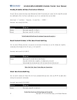
Jamming I/O Setup
GPS jamming detection can be enabled to trigger output devices likes lamp or buzzer when the jamming is detected. The
data will be saved to flash memory during the period of jamming.
Either one or both of the device two output I/Os can be defined for jamming detection. Pull high/low or high/low pulse
output signaling settings are available.
The external power source is required for triggering output devices, or the device will detect jamming without warning.
When the output I/Os are assigned for jamming detection, any other command to trigger the output I/Os will be invalid
(no actions).
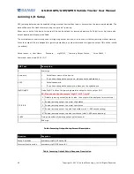
Setup format: #
「
User Name
」
,
「
Password
」
,
「
cfgO1/O2
」
,
「
Jamming Output Status
」
,
「
Pulse Width
」
*
Command: #username,0000,JD,1*
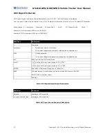
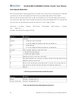
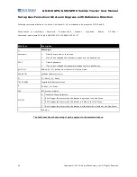
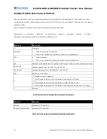
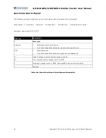
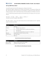
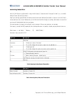
Table: Jamming Output Setup Format Description
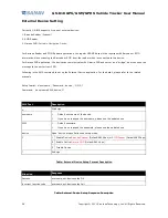
Table: Jamming Output Setup Response Description
SMS Text
Description
#
Start sign.
username
Default user name of the device.
If you have changed the username, please use the updated one.
0000
Default password.
If you have changed the password, please use the updated one.
cfgO1/cfgO2
Mode “cfgO1” defines the jamming detection output is set to output I/O1.
PS: Please note the characters “cfgO1”, NOT “cfg01”
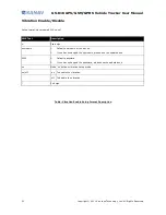
0 Disable jamming output (default value, the output will be assigned for normal use)
1 Enable jamming output to normal High status
2 Enable jamming output to normal Low status
3* Enable jamming output to pulse High status (with 1~999 second setting)
0/1/2/3/4
4* Enable jamming output to pulse Low status (with 1~999 second setting)
1~999
Time pulse width of jamming output pulse (second)
*
End sign.
Situation
Response
Setup Succeeds
username, cfgO1/O2 setup OK.
Incorrect function code
username, cfgO1/O2 setup fail.


