3-16
3. Disassembly and Reassembly
- 이 문서는 삼성전자의 기술 자산으로 승인자만이 사용할 수 있습니다 -
- This Document can not be used without Samsung's authorization -
R530/R730
Part
Picture
Description
LCD
Ass'y
(17")
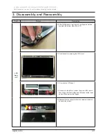
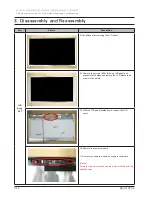
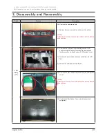
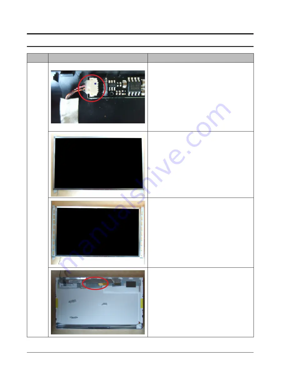
2) Disassemble the connector from the camera module as
shown in the picture.
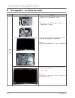
3) Conditions after removing the LCD panel.
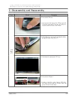
34. Remove the screws (6EA) for fixing LCD panel and
bracket of both sides and remove the LCD brackets as
shown in the picture.
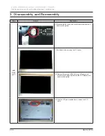
35. With the LCD panel upside down, remove the LCD
cable.
Summary of Contents for R530
Page 5: ...iii Contents This Document can not be used without Samsung s authorization R530 R730...
Page 64: ...6 40 6 Material List This Document can not be used without Samsung s authorization R530 R730...
Page 240: ...4 23 4 Troubleshooting This Document can not be used without Samsung s authorization R530 R730...
Page 241: ...4 24 4 Troubleshooting This Document can not be used without Samsung s authorization R530 R730...
Page 249: ...4 32 4 Troubleshooting This Document can not be used without Samsung s authorization R530 R730...

