


CHAPTER
12
.
Error! Use the Home tab to apply
제목
1,
장
제목
1 to the text that you want to appear here.
2-58
© SAMSUNG Electronics Co., Ltd.
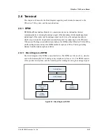
2.6.1.2 Block Diagram of Door Phone
The block diagram of the door phone, which is used, connected to the OfficeServ 7100
system, OfficeServ 7100, is as follows:
Figure 2.34 Block Diagram of Door Phone
2.6.1.3 Main Function
The main function of the DPIM is as follows:
Micro-controller Unit (MCU)
The signal transmitted from the DPIM PCM digital transfer part is conversed into the
analogue signal in HFC(High Feature CODEC). At this time, TL084 whose audio quality is
good is used as an amplifier to amplify the analogue signal, which was transmitted from the
door box, and the displayed signal. Since the input resistance of TL084 should be great,
100 k
Ω
is used as an input resistance.
In the matching part, T5692 is used along with the trans of the door box. The resistance of
1 k
Ω
(R14) is the resistance value when two trans have the best quality of transfer.
Also, since the resistance of 100 k
Ω
(R9, R10) uses the signals transmitted and received
from/to the trans by mixing them, it is a balance resistance for decreasing the input of the
signals, which are transmitted to the speaker, to the micro input of the HFC(NO. 19. pin).
Door Lock Control Part
In the DPIM, the locker, which provides a function to open the door to a visitor, can be
mounted. The general locker uses AC 100 V, which is turned on/off by using a relay as a
switch. At this time, the relay control port of the MCU is P10(No. 48 pin), and this port is
the key scan port in a digital phone. The diode of the relay control TR.(MMBT 2222, Q1)
output end(1N4148,D6) is used to clear the counter electro-motive force. The cap and the
resistance of the both ends of the relay are for preventing the spark occurring at the relay
contact.
DPIM Interface
MIC Interface
SPK Interface
Summary of Contents for OFFICESERV 7100
Page 1: ...Ed 00 OfficeServ 7100 Service Manual ...
Page 33: ...OfficeServ 7100 Service Manual SAMSUNG Electronics Co Ltd 1 15 ...
Page 189: ...OfficeServ 7100 Service Manual SAMSUNG Electronics Co Ltd 5 3 Soldering Side ...
Page 195: ...OfficeServ 7100 Service Manual SAMSUNG Electronics Co Ltd 5 9 5 7 TEPRI2 Board Part Side ...
Page 197: ...OfficeServ 7100 Service Manual SAMSUNG Electronics Co Ltd 5 11 5 8 8COMBO Part Side ...
Page 199: ...OfficeServ 7100 Service Manual SAMSUNG Electronics Co Ltd 5 13 5 9 16DLI2 Part Side ...
Page 201: ...OfficeServ 7100 Service Manual SAMSUNG Electronics Co Ltd 5 15 5 10 MGI16 MGI32 Part Side ...
Page 203: ...OfficeServ 7100 Service Manual SAMSUNG Electronics Co Ltd 5 17 5 11 16SLI2 16MWSLI Part Side ...
Page 205: ...OfficeServ 7100 Service Manual SAMSUNG Electronics Co Ltd 5 19 5 12 8TRK Board Part Side ...
Page 207: ...OfficeServ 7100 Service Manual SAMSUNG Electronics Co Ltd 5 21 5 13 PLIM Board Part Side ...


