


OfficeServ 7100 Service Manual
© SAMSUNG Electronics Co., Ltd.
2-1
CHAPTER 2.
Circuit Overview
This chapter describes the circuit configuration and major features for each component of
the OfficeServ 7100 system.
2.1 System Structure
This section describes the physical structure and the communication structure between the
cabinets of the OfficeServ 7100 system.
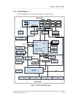
2.1.1 Block Diagram
The physical structure of the OfficeServ 7100 system is as shown in the figure below:
Figure 2.1 Physical Structure of the OfficeServ 7100 System
Power
+5 V
-5 V
+12 V
+3.3 V-54V54 V
Mother Board
SLOT1
SLOT2
MISC
LAN
SIO
MP10/11P10/11
Summary of Contents for OFFICESERV 7100
Page 1: ...Ed 00 OfficeServ 7100 Service Manual ...
Page 33: ...OfficeServ 7100 Service Manual SAMSUNG Electronics Co Ltd 1 15 ...
Page 189: ...OfficeServ 7100 Service Manual SAMSUNG Electronics Co Ltd 5 3 Soldering Side ...
Page 195: ...OfficeServ 7100 Service Manual SAMSUNG Electronics Co Ltd 5 9 5 7 TEPRI2 Board Part Side ...
Page 197: ...OfficeServ 7100 Service Manual SAMSUNG Electronics Co Ltd 5 11 5 8 8COMBO Part Side ...
Page 199: ...OfficeServ 7100 Service Manual SAMSUNG Electronics Co Ltd 5 13 5 9 16DLI2 Part Side ...
Page 201: ...OfficeServ 7100 Service Manual SAMSUNG Electronics Co Ltd 5 15 5 10 MGI16 MGI32 Part Side ...
Page 203: ...OfficeServ 7100 Service Manual SAMSUNG Electronics Co Ltd 5 17 5 11 16SLI2 16MWSLI Part Side ...
Page 205: ...OfficeServ 7100 Service Manual SAMSUNG Electronics Co Ltd 5 19 5 12 8TRK Board Part Side ...
Page 207: ...OfficeServ 7100 Service Manual SAMSUNG Electronics Co Ltd 5 21 5 13 PLIM Board Part Side ...


