CHAPTER 1.
Error! Use the Home tab to apply
제목
1,
장
제목
1 to the text that you want to appear here.
1-8
© SAMSUNG Electronics Co., Ltd.
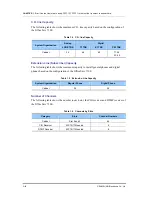
C.O. line Capacity
The following table shows the maximum C.O. line capacity based on the configuration of
the OfficeServ 7100.
Table 1.4 C.O. line Capacity
System Organization
Analog
Digital
LOOP TRK
T1 TRK
E1 TRK
PRI TRK
Cabinet 24
48
60
T1:
48
E1: 60
Extension Line (Subscriber) Capacity
The following table shows the maximum capacity to install general phones and digital
phones based on the configuration of the OfficeServ 7100:
Table 1.5 Extension Line Capacity
System Organization
Regular Phone
Digital Phone
Cabinet 24
24
Number of Channels
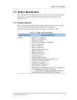
The following table shows the number in each slot, the CID receiver and DTMF receiver of
the OfficeServ 7100:
Table 1.6 Channels by Slots
Category
Slots
Channel Numbers
Cabinet
Slot 2 and 3
64
CID Receiver
MP10/11 Mounted
4
DTMF Receiver
MP10/11 Mounted
8
Summary of Contents for OFFICESERV 7100
Page 1: ...Ed 00 OfficeServ 7100 Service Manual ...
Page 33: ...OfficeServ 7100 Service Manual SAMSUNG Electronics Co Ltd 1 15 ...
Page 189: ...OfficeServ 7100 Service Manual SAMSUNG Electronics Co Ltd 5 3 Soldering Side ...
Page 195: ...OfficeServ 7100 Service Manual SAMSUNG Electronics Co Ltd 5 9 5 7 TEPRI2 Board Part Side ...
Page 197: ...OfficeServ 7100 Service Manual SAMSUNG Electronics Co Ltd 5 11 5 8 8COMBO Part Side ...
Page 199: ...OfficeServ 7100 Service Manual SAMSUNG Electronics Co Ltd 5 13 5 9 16DLI2 Part Side ...
Page 201: ...OfficeServ 7100 Service Manual SAMSUNG Electronics Co Ltd 5 15 5 10 MGI16 MGI32 Part Side ...
Page 203: ...OfficeServ 7100 Service Manual SAMSUNG Electronics Co Ltd 5 17 5 11 16SLI2 16MWSLI Part Side ...
Page 205: ...OfficeServ 7100 Service Manual SAMSUNG Electronics Co Ltd 5 19 5 12 8TRK Board Part Side ...
Page 207: ...OfficeServ 7100 Service Manual SAMSUNG Electronics Co Ltd 5 21 5 13 PLIM Board Part Side ...


