


OfficeServ 7100 Service Manual
© SAMSUNG Electronics Co., Ltd.
2-55
2.5.16 MODEM Board
A modem used in OfficeServ 7100 system should support 2 wire full duplex, and this board
is the board that can be shared with the modem of iDCS 500 system. Modem board is
mounted on LOC1 of MP40 board. When the board is mounted, be careful of the direction
of the modem board. Modem board is connected to OfficeServ 7100 system through V.24
interface and uses the modem chip for central office that PCM highway interface is
available. In addition, the modem board supports the V.90 protocol. Modem board is
controlled through the serial communication type in OfficeServ 7100 and the command used
is standard AT command. SMC2 is allocated and used as the serial port for modem control.
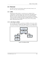
2.5.16.1 Block Diagram
The modem board block diagram is as follows:
Figure 2.31 Modem Board Block Diagram
MCU
Addr
MDP
COMBO
PCM
Interface
Memory
Serial
Host Intf.
Addr
DATA
Tx/Rx
Control
DATA
Summary of Contents for OFFICESERV 7100
Page 1: ...Ed 00 OfficeServ 7100 Service Manual ...
Page 33: ...OfficeServ 7100 Service Manual SAMSUNG Electronics Co Ltd 1 15 ...
Page 189: ...OfficeServ 7100 Service Manual SAMSUNG Electronics Co Ltd 5 3 Soldering Side ...
Page 195: ...OfficeServ 7100 Service Manual SAMSUNG Electronics Co Ltd 5 9 5 7 TEPRI2 Board Part Side ...
Page 197: ...OfficeServ 7100 Service Manual SAMSUNG Electronics Co Ltd 5 11 5 8 8COMBO Part Side ...
Page 199: ...OfficeServ 7100 Service Manual SAMSUNG Electronics Co Ltd 5 13 5 9 16DLI2 Part Side ...
Page 201: ...OfficeServ 7100 Service Manual SAMSUNG Electronics Co Ltd 5 15 5 10 MGI16 MGI32 Part Side ...
Page 203: ...OfficeServ 7100 Service Manual SAMSUNG Electronics Co Ltd 5 17 5 11 16SLI2 16MWSLI Part Side ...
Page 205: ...OfficeServ 7100 Service Manual SAMSUNG Electronics Co Ltd 5 19 5 12 8TRK Board Part Side ...
Page 207: ...OfficeServ 7100 Service Manual SAMSUNG Electronics Co Ltd 5 21 5 13 PLIM Board Part Side ...


