


7
Adjusting the limit switch
The positioner version with an inductive limit
switch has one adjustable tag (1) mounted
on the shaft which operates the proximity
switch (3).
For operation of the inductive limit switch,
the corresponding switching amplifier (see
section 3.2.1) must be connected to the out-
put.
If the tag (1) is inside the field of the switch,
the switch assumes a high resistance. If the
tag is outside of the field, the switch assumes
a low resistance.
Normally, the limit switch is adjusted such
that it will provide a signal in both end posi-
tions of the valve. The switch, however, can
also be adjusted to indicate intermediate
valve positions.
The desired switching function, i.e. whether
the output relay shall be picked up or re-
leased when the tag has entered the field,
has to be determined, if necessary, at the
switching amplifier.
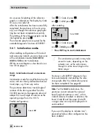
Setting the switching point
:
Note:
During adjustment or testing, the
switching point must always be approached
from mid-position (50 %).
To ensure safe switching under any ambient
conditions, the switching point should be ad-
justed to a value of approx. 5 % before the
mechanical stop (OPEN – CLOSED).
78
EB 8384-4 EN
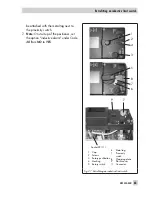
Adjusting the limit switch
Fig. 26 · Adjustment of the limit switch
Adjustment screw (2)
Tag (1) Proximity switch (3)
Summary of Contents for 3730-4
Page 2: ...2 EB 8384 4 EN...
Page 127: ......
Page 188: ...188 EB 8384 4 EN...
Page 189: ...EB 8384 4 EN 189...
Page 190: ...190 EB 8384 4 EN...
Page 191: ...EB 8384 4 EN 191...
Page 192: ...192 EB 8384 4 EN...
Page 193: ...EB 8384 4 EN 193...
Page 194: ...194 EB 8384 4 EN...
Page 195: ...EB 8384 4 EN 195...
Page 196: ...196 EB 8384 4 EN...
Page 197: ...EB 8384 4 EN 197...
Page 198: ...198 EB 8384 4 EN...
Page 199: ...EB 8384 4 EN 199...
Page 206: ...206 EB 8384 4 EN...
Page 207: ...EB 8384 4 EN 207...
Page 208: ...208 EB 8384 4 EN...
Page 209: ...EB 8384 4 EN 209...
Page 210: ...210 EB 8384 4 EN...
Page 211: ...EB 8384 4 EN 211...


