R5
SUPREME - Navigation System
ELECTRICAL INTERFACES
7000 118-301, A
Page 141
Pin
In/Out
Signal Name
Signal Type
R5 Signal Cable
DSUB-OPEN
19
In
General I/O 2
– In
Binary
White / Pink
20
-
GND
Binary
Pink / Brown
21
-
GND
Binary
White / Blue
22
In
General I/O 0
– In
Binary
Brown / Blue
23
Out
General I/O 3 - Out
Binary
White / Red
24
-
NOT CONNECTED
-
Brown / Red
25
-
NOT CONNECTED
-
26
-
NOT CONNECTED
-
Table 14
– 26-pin High Density D-sub
13.1.1.3 Power port
Pin In/Out Signal Name Signal Type R5 Power Cable
1
In
PWR +
24 VDC
Red
2
In
PWG GND
0 VDC
Black
3
-
-
-
Brown
4
-
-
-
Orange
Table 15
– CDU Power port
13.1.1.4 GND Screw
– M6
13.1.2 CDU Front hatch:
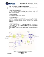
Figure 108- CDU Front ports
13.1.2.1 USB Host Type A
USB 2.0.
Supports FAT32 file systems and USB keyboards
13.1.2.2 CDU Pilot Plug RS-422
Only active in AIS or Combined AIS / Nav installations.
This bi-directional port is routed over Ethernet to the Transponder.
Summary of Contents for R5 SUPREME AIS
Page 1: ...OPERATION INSTALLATION MANUAL Saab TransponderTech R5 SUPREME Navigation System ...
Page 2: ...This page is intentionally empty ...
Page 60: ...R5 SUPREME Navigation System OPERATION 7000 118 301 A3 Page 60 5 4 System Menus Tree View ...
Page 103: ...R5 SUPREME Navigation System OPERATION 7000 118 301 A Page 103 Figure 92 Update Software ...


