background image


 R5 

SUPREME - Navigation System


INTERPRETATIONS OF INPUT SENTENCES 

7000 118-301, A 


Page 136 

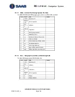
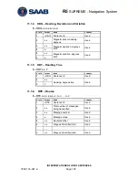
11.1.7 

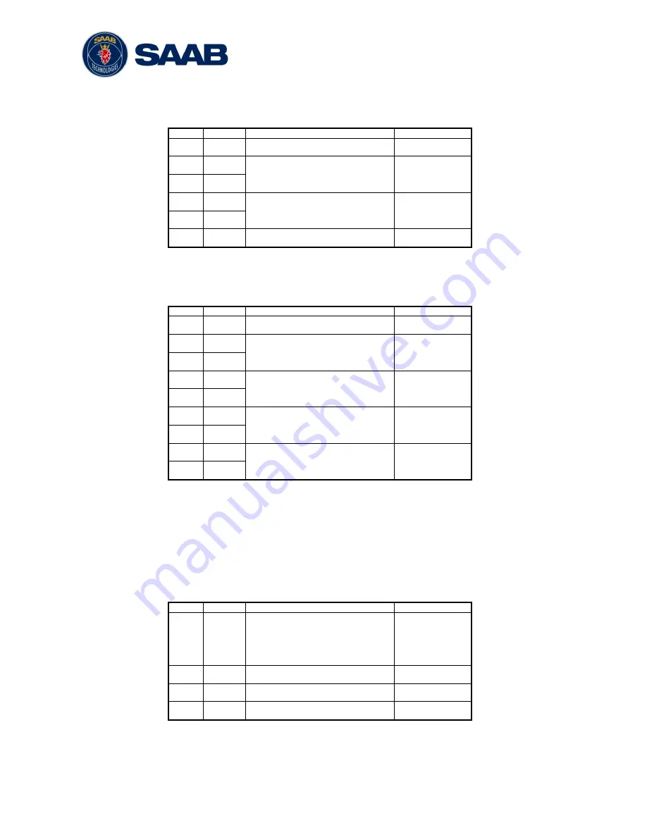
WPL 

– Waypoint location 

$--WPL,llll.ll,a,yyyy.yy,a,c--c 

Field  Format 

Name 

Comment 

--WPL 

Sentence Id 

Used 

llll.ll 

Waypoint latitude, N/S 

Used 

yyyy.yy 

Waypoint longitude, E/W 

Used 

c--c 

Waypoint identifier 

Used 

11.1.8 

VHW 

– Water speed and heading 

$--VHW,x.x,T,x.x,M,x.x,N,x.x,K 

Field  Format 

Name 

Comment 

--VHW 

Sentence Id 

Used 

x.x 

Heading, degrees true 

Used 

x.x 

Heading, degrees magnetic 

Used 

x.x 

Speed, knots 

Used 

x.x 

Speed, km/h 

Not used 

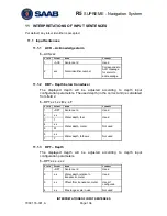
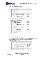
11.2  Input Sentences, Old NMEA Versions 

11.2.1 

Rnn 

– Routes (old NMEA versions) 

Can only be used for input of working (active) route. It is recommended to use the 

RTE


sentence instead if this sentence. Per default, any talker ID is accepted. 

$--

Rnn,cccc,cccc,…,cccc 

Field  Format 

Name 

Comment 

--Rnn 

Sentence id and route identifier 

‗nn‘ is 
interpreted as 
route identifier 
(00 

– 99). 

cccc 

Waypoint identifier (first) 

Used 

.. 

… 

… 

… 

15 

cccc 

Waypoint identifier (last) 

Used 

Summary of Contents for R5 SUPREME AIS

Page 1: ...OPERATION INSTALLATION MANUAL Saab TransponderTech R5 SUPREME Navigation System ...

Page 2: ...This page is intentionally empty ...

Page 3: ...oever based on the contents or lack of contents in the manual iii Software This manual reflects the capabilities of R5 SUPREME Control and Display Unit software 1 0 1 and R4 Navigation Sensor software 6 8 S7 iv Manual Part Number and Revision Part number 7000 118 301 revision A3 v Safety Instructions Note the following compass safe distances Equipment vi Standard magnetic compass vii Steering magn...

Page 4: ... Page 4 x Contact Information For installation service and technical support please contact your local Saab TransponderTech representative A list of dealers and service stations can be found on the corresponding product page at www saabgroup com transpondertech ...

Page 5: ... Navigation Antenna 25 2 6 Mount the R5 NAV Junction Box if applicable 28 2 7 System interconnection without R5 NAV Junction box 32 2 8 Electrical Installation 34 3 Concepts and Terminology 37 4 Configuration 39 4 1 Configuration Wizard 39 4 2 Configuration Parameters 41 5 Operation 56 5 1 Buttons and LEDs on R5 SUPREME CDU 56 5 2 LEDs on R4 Navigation Sensor 58 5 3 Change Settings of a Parameter ...

Page 6: ... Contacting Support 119 9 Serial Communication Interfaces 120 9 1 Input Sentences 120 9 2 Output Sentences 120 10 Interpretations of Output Sentences 123 10 1 Output Sentences GPS 123 10 2 Output Sentences Navigation 129 10 3 Output Sentences Old NMEA Versions 133 11 Interpretations of Input Sentences 134 11 1 Input Sentences 134 11 2 Input Sentences Old NMEA Versions 136 12 Alternate System Setup...

Page 7: ...SUPREME Navigation System SYSTEM OVERVIEW 7000 118 301 A3 Page 7 14 4 R5 NAV Junction Box Physical Size and Mechanical Drawing 153 15 Appendix B License 154 15 1 Copy of the GNU General Public License 154 ...

Page 8: ...le to create edit and modify routes and waypoints navigate following a route plot the route view sensor data configure the system as well as supervise the system status The R4 GPS Navigation Sensor features a high precision GPS receiver capable of receiving WAAS EGNOS and MSAS differential corrections The R4 DGPS Navigation Sensor has all the features of the GPS Sensor as well as a dual channel be...

Page 9: ...up to 4000 individually named waypoints and up to 128 different routes Man Over Board MOB and Event Mark functionality Two trip log counters with indication of average speed and accumulated time during motion Anchor Watch position deviation alarm Scheduled Alerts user configurable time alarms and time to ETA alarms Time frame related to UTC or user defined local offset Synchronization of waypoint ...

Page 10: ...er Cable 7000 118 077 1 1 R5 Signal cable DSUB OPEN 2m For use without Junction Box 7000 118 078 0 1 R5 Signal cable DSUB DSUB 2m For Junction Box connection 7000 118 286 1 0 R5 NAV Junction Box 7000 118 121 1 0 R4 Navigation Sensor Power and Signal Cable Used without Junction Box 7000 109 011 0 1 R5 NAV Sensor Cable For Junction Box connection 7000 118 122 1 0 Table 1 R5 SUPREME Navigation System...

Page 11: ...l cable DSUB DSUB 2m Transponder to AIS Junction Box 7000 118 286 2 R5 AIS Junction Box For combined AIS NAV configuration 7000 118 120 1 VHF Antenna BA 1012 for R5 SUPREME AIS Transponder 7000 000 077 AT575 68 GPS Antenna for R5 SUPREME AIS Transponder 7000 000 135 MA700 GPS Antenna incl 10m cable for R5 SUPREME AIS Transponder 7000 000 485 AC Marine GPS VHF Antenna with diplexer for R5 SUPREME A...

Page 12: ... classification for the system Name Part number IEC 60945 installation category R5 SUPREME CDU 7000 118 530 Protected R5 NAV Junction box 7000 118 121 Protected R4 GPS Navigation Sensor 7000 109 141 Protected R4 DGPS Navigation Sensor 7000 109 140 Protected MGA 2 GPS Antenna 7000 000 263 Exposed MGL 4 Combined GPS Beacon Antenna 7000 000 359 Exposed ...

Page 13: ...air 24 x 0 33 mm2 Length 2 m Connector 26 pole H D D SUB female Flame retardant IEC60332 1 Interconnection Specification Color coding DIN 47100 D SUB Pin Open End colour 1 White 2 Brown 3 Green 4 Yellow 5 Grey 6 Pink 7 Blue 8 Red 9 Black 10 Violet 11 Grey Pink 12 Red Blue 13 White Green 14 Brown Green 15 White Yellow 16 Yellow Brown 17 White Grey 18 Grey Brown 19 White Pink 20 Pink Brown 21 White ...

Page 14: ...tor 2 x 26 pole H D D SUB female to male Flame retardant IEC60332 1 Interconnection Straight connection on all pins 2 3 3 R5 Power Cable Marking 7000 118 077 Application R5 CDU power port to R5 NAV Junction box or external power Type Unshielded 4 wire cable x 1 3 mm2 Length 2 m Diameter 6 mm Connector ConXall Mini Con X 6382 4SG 311 female to open ends Interconnection specification Pin Cable Colou...

Page 15: ... White 2 Green 3 Brown 4 Brown Green 5 Yellow 6 Yellow Brown 7 Grey 8 Pink 9 Blue 10 Black 11 Purple 12 NC 13 Red Blue 14 White Green 15 White Yellow 16 Grey Pink 17 Red 18 White Grey Table 7 Pinout for R4 Sensor Power and Signal Cable 2 3 5 R5 Navigation Sensor Cable used with Junction Box Marking 7000 118 122 A1 Application R4 Sensor power and data port to R5 NAV Junction box Type 9 Pair x 0 25 ...

Page 16: ...gth See section 2 5 2 Connector TNC Male 2 3 7 R5 SUPREME Ethernet Cable Type Cat 7 LSZH FR IEC 60332 1 Length 5 m Diameter 6 5 mm Connector RJ 45 Part number 7000 000 525 2 3 8 Minimum cable bending radius When installing the cables the recommended minimum bending radiuses are as follows Signal and power cables 10 times cable diameter Coaxial cables 5 times cable diameter ...

Page 17: ...ame as above plus a transponder with additional GPS and VHF antennas and an AIS junction box As multiple redundant navigation systems o Several instances of the standalone nav system connected to the same network configured to synchronize navigation data One system with extra Navigation display in view only mode Master Slave Mode o On instance of the standalone system plus an additional CDU connec...

Page 18: ...er Port 1 Speed Log Alarm Relay User Port 4 User Port 3 User Port 2 Alarm ACK R4 GPS Navigation Sensor or R4 DGPS Navigation Sensor D GPS Antenna R5 NAV Junction Box 4 GP I O R5 NAV Sensor Cable External power 24 VDC R5 Signal Cable R5 Power Cable Figure 1 Standalone R5 NAV with NAV Junction Box System Port User Port 1 User Port 2 Speed Log Alarm Output RS 422 Ports User Port 3 User Port 4 R4 Sens...

Page 19: ...m screw terminal for system interconnection b Connect the R5 SUPREME CDU Sensor port to the R4 Navigation Sensor System port c Connect external systems 7 For Redundant or Slave display configuration a Connect the CDU to a network or directly to another CDU using the R5 Ethernet Cable or equivalent 8 For Combined NAV and AIS configuration a Install the R5 Supreme Transponder as detailed in the R5 S...

Page 20: ...pass 2 3 2 R5 SUPREME CDU Mounting Options The R5 SUPREME transponder and CDU are equipped with power and interface connectors designed to prevent water ingress However the SD USB and Pilot connectors under the CDU front hatch are protected by the hatch only the connectors are NOT water proof It is therefore recommended to keep the CDU hatch closed when possible The hatch has a locking mechanism d...

Page 21: ... Mount Panel mounting will reduce bridge clutter and reduce the space needed for installation A cutout fitting the CDU profile must be made See Chapter 14 for dimensions The CDU is fastened in place using the pin screw nut and washer nut from the included mounting kit 7000 118 315 ...

Page 22: ...panel mount The CDU can be attached to the panel mount frame using the mounting kit 7000 118 315 included with the R5 CDU Figure 3 R5 SUPREME CDU Mounting frame panel mount The cutout dimensions may need to be increased somewhat compared to the R4 MKD cutout as the R5 CDU is slightly wider ...

Page 23: ...23 2 3 3 R5 CDU clearance area Leave a clearance around the R5 NAV Junction Box to facilitate service and installation See below figure for minimum recommended clearance area measurements in mm Figure 4 CDU Gimbal mount clearance Figure 5 CDU Panel mount clearance ...

Page 24: ...as where there is a high flow of humid salt air Avoid places with high levels of vibrations and shocks Ensure that there is enough airflow to avoid high ambient temperatures Ensure that the different cables can be connected without violating their maximum bending radius The unit can affect magnetic compasses The minimum compass safe distance is 0 6 meters to a standard magnetic compass and 0 4 met...

Page 25: ...standard antenna mount not included Note Antennas threaded onto a mount should be tightened only by hand Do not tighten the antenna by turning on the antenna cover instead hold the mounting shaft located at the bottom of the antenna and tighten by hand Do not thread the pipe deeper than into the antenna Do not use tools to install the antenna on the pipe as this may cause damage Damage caused by o...

Page 26: ...ard antenna Cable Type Max length with MGA 2 or MGL 4 RG 58 20 m RG 400 30 m RG 223 30 m RG 214 51 m RG 225 60 m Table 9 Recommended Maximum GPS Cable Length Maximum cable length is calculated as Maximum cable length allowed total loss cable attenuation per meter 2 5 3 Cable Mounting Coaxial cables should be installed in separate signal cable channels tubes and at least 10 cm away from power suppl...

Page 27: ...R5 SUPREME Navigation System INSTALLATION 7000 118 301 A3 Page 27 Secure the cable properly near the cable ends 2 5 4 Grounding The MGA 2 and MGL 4 antennas do not require any antenna ground connection ...

Page 28: ... output alarm acknowledgement and speed log output signals The R5 NAV Junction Box also has built in fuses for the R5 CDU and the R4 Navigation Sensor 2 6 1 Junction Box Location The R5 Signal Cables connecting the R5 CDU and the R4 Sensor to the Junction box are 2m long hence this is the maximum distance between the Junction Box and the CDU or Sensor units The R5 NAV Junction Box is made from EMI...

Page 29: ...R5 SUPREME Navigation System INSTALLATION 7000 118 301 A3 Page 29 Figure 7 Clearance Area for R5 AIS NAV Junction boxes ...

Page 30: ... glands mounted the maximum supported cable diameter is 19 5mm Shielded cables should be stripped down to the shielding and fastened with cable ties There are eleven cable tie fastening points on the circuit board one for every anti vibration gland on the junction box Make sure that the cable shielding touches the tin plated area at the fastening point The maximum supported cable tie width is 4 5m...

Page 31: ...Cable R5 Power Cable Figure 8 Installation with R5 NAV Junction Box 1 Connect the R5 SUPREME CDU to the junction box by using the R5 Signal Cable DSUB DSUB and the R5 Power Cable Connect the R4 Navigation Sensor to the junction box by using the R5 NAV Sensor Cable 2 Connect the GPS antenna to the R4 Navigation Sensor 3 Connect Alarm Relay signal to bridge alarm 4 Connect additional external sensor...

Page 32: ...ion used in this case The Navigation sensor cable is connected by an 18 pin ConXall connector to the sensor and supplies several different interfaces as indicated by Figure 9 The cable is also used to apply power to the sensor Important The shield of the R4 Navigation Sensor power and signal cable 7000 109 011 is referenced to the negative DC supply For the same reason don t connect the Navigation...

Page 33: ...ink RX B Red Blue RX A Green RX A Yellow RX B Purple TX B Black TX A R5 CDU Sensor port R4 Sensor System Port CDU Pin Signal Name R5 Signal Cable DSUB OPEN R4 Navigation sensor signal power cable Signal Name Sensor Pin 1 Sensor Port TxB White Yellow System Port RxB 5 2 Sensor Port TxA Brown Green System Port RxA 2 11 Sensor Port RxB Grey Pink Purple System Port TxB 11 12 Sensor Port RxA Red Blue B...

Page 34: ...ect to the R5 SUPREME CDU via the Sensor port on the R5 SUPREME CDU The TX signal of the System port shall be connected to the RX signals of Sensor port on the CDU and the RX signals of the System port shall be connected to the TX signals of the R5 SUPREME CDU Sensor port 2 8 2 2 User Port 1 The port is bidirectional and can be used to connect to external equipment such as an ECDIS system or to ex...

Page 35: ...ormally active supplying power When an alarm is activated the port will go low and supply 0 VDC The port will remain low until the alarm is deactivated Once the alarm is deactivated the port will go high supplying power again If the R5 NAV Junction box is installed this signal will be connected to the Junction box internal alarm relay 2 8 2 5 Alarm Acknowledge Binary Port The Alarm Acknowledge bin...

Page 36: ... used to connect to external equipment and sensors such as a compass or depth sensor To receive data on the ports their RX signals shall be connected to the TX signals of the external equipment For an external equipment to receive data from the R5 SUPREME Navigation System via the ports the TX signals of the ports shall be connected to the RX signals of the external equipment It is up to the user ...

Page 37: ...route between two consecutive waypoints A route with the waypoints A B and C has two legs A to B and B to C For each leg in a route the navigation algorithm RAIM accuracy level and cross track error XTE limit can be set RAIM RAIM stands for Receiver Autonomous Integrity Monitoring and is a GPS integrity monitoring scheme that evaluates the quality of the position data and is able under normal circ...

Page 38: ... and cuts across all meridians at the same angle Waypoint Pass Criterion The criterion used to determine when a waypoint in the active route is considered passed The waypoint pass criterion can be any of Manual Distance Bisector Line and Perpendicular Line Manual Waypoint Pass Criterion Using this pass criterion the waypoint is only considered passed when the operator skips the waypoint Distance W...

Page 39: ...SUPREME System The following sections describe the different steps in the configuration wizard 4 1 1 Calibration View Figure 10 Calibration View The first time the R5 SUPREME CDU is used the touch screen needs to be calibrated A cross will be shown on the screen at several locations Press on the cross each time it appears to calibrate the touch screen Try to hit the center of the cross as accurate...

Page 40: ...U Master Slave Mode Only If the R5 SUPREME CDU is configured to be used as a slave display to an existing R5 SUPREME Navigation system the master CDU must be selected on the LWE network in order to receive GPS data and synchronize waypoints routes and configurations Make sure that the master R5 SUPREME Navigation System is powered on and is connected to the LWE network On the slave display press t...

Page 41: ...tically switch to the Position view when configured as a Navigation System Figure 14 Connection View 4 2 Configuration Parameters The following sections lists and describes all the parameters that can be configured in the R5 SUPREME Navigation System All the configuration sub menus can be found under Main Menu Maintenance Configuration 4 2 1 Navigation The Navigation Configuration view is accessed...

Page 42: ...ing towards the first waypoint and t1 will be output as from waypoint in route RTE message The newly created t1 waypoint will be visible in the active route but it will not be added to the waypoint database Default RAIM Level This is the default RAIM level that will be used by the system if no specific RAIM level is set on the current leg of the active route The currently used RAIM level is always...

Page 43: ... time specified by the Average SOG Time parameter The estimated time is accurate if the course is directly towards to the waypoint Average SOG Time The Average SOG Time parameter defines the time period over which average speed is calculated when estimating time of arrival ETA to the end of the active route and Time To Go TTG to the next waypoint RTE Rnn WP Limit Determines the maximum number of r...

Page 44: ...his setting the system will use signals from IALA radio beacon stations as source for differential corrections This setting is only available when using an R4 DGPS Navigation Sensor the DGPS configuration SBAS This setting makes the system use SBAS satellite signals as source for differential corrections User Port 1 This setting will command the system to apply external differential corrections re...

Page 45: ...alue is zero and increasing the value will increase the level of COG smoothing As with the SOG smoothing parameter the setting of this parameter depends upon the expected dynamics of the vessel If a ship is highly dynamic this value should be set to a lower value since the filtering window needs be shorter in time resulting in a more responsive measurement However if a vessel is very large and has...

Page 46: ... sets the frequency selection mode of the R4 DGPS Navigation Sensor internal radio beacon receiver The mode can be Frequency Scan Manual or Database Auto The Database mode is only available when the Beacon Database is enabled In Frequency Scan mode the beacon receiver will search available frequencies and tune to the strongest beacon signal In this mode the R4 Navigation Sensor continuously perfor...

Page 47: ...his parameter is only available when Bit Rate Mode is set to manual Beacon Database The Beacon Database parameter is used to enable or disable the Beacon Database When the parameter is set to off the Beacon Database view will not be available See section 5 11 6 for more information about the Beacon Database view 4 2 5 GPS Antenna Offset The GPS antenna offset feature can adjust the system position...

Page 48: ... and the buttons of the R5 SUPREME CDU can be controlled manually or automatically using the light sensor on the front of the CDU The default value of the LCD backlight is 80 which corresponds to approximately 550 Cd m2 To quickly turn off all backlight on the R5 SUPREME CDU press once on the PWR button on the front of the CDU This will completely turn off all backlight for the LCD LED s and butto...

Page 49: ...light button illumination and LED intensity will automatically be controlled with the light sensor on the front of the R5 SUPREME CDU The less ambient light registered by the light sensor the lower percentage of backlight and brightness will be used Master Level The master level controls the overall brightness level in percent of the selected maximum level for LCD backlight LED intensity and butto...

Page 50: ...aker when a new DGPS RTCM Type16 message has been received Man Over Board Controls the behavior of the R5 SUPREME CDU speaker when a MOB waypoint has been activated 4 2 8 Time This view is accessed by pressing Main Maintenance Configuration Display Time Parameter Name Description Time Zone This parameter defines if the times that are displayed in the R5 SUPREME CDU should be in UTC or LOC local ti...

Page 51: ... CDU It can be calculated in meters m or feet ft 4 2 10 CDU Password This view is accessed by pressing Main Maintenance Configuration Display CDU Password Parameter Name Description New CDU Password Changes the password for the R5 SUPREME CDU The default CDU password is cdupwd Restore Password Key It is possible to restore the CDU password to the default value above with a secret restore key To ob...

Page 52: ...accessed by pressing Main Maintenance Configuration Interface Port Rates In this view it is possible to configure the baud rate for the four different User ports in the R5 Navigation System as well as the pulse rate of the Speed Log output User Port 1 has a maximum baud rate of 38400 bps User Port 2 has a maximum baud rate of 19200 bps User Port 3 and 4 can be configured up to 115200 bps The highe...

Page 53: ...t possible to only use a specific NMEA sentence for heading data Input Talker ID This parameter makes it possible to only use sentences from a specific talker having a specific NMEA talker ID for the heading data 4 2 15 Depth Data Port This view is accessed by pressing Main Maintenance Configuration Interface Input Depth Data Port Parameter Name Description Input Port Specifies the input port that...

Page 54: ...o only use a specific NMEA sentence for routes Input of routes with Rnn sentence will always be considered as a working route i e it will replace the current active route in the system Input of routes with RTE sentence can either mean working route or complete route depending on information in the RTE sentence A working route will replace the currently active route A complete route will be added t...

Page 55: ...y if the R5 SUPREME CDU is used together with an R4 DGPS Navigation Sensor with routing software version 1 07 or higher Current routing software of the Navigation sensor can be viewed in the SW HW Info view described in section 5 11 10 If this function is available an RTCM option will be added to the list of output messages in the User Port 2 Output Configuration view as illustrated below Figure 1...

Page 56: ...igation System Green Safe state Estimated position error smaller than RAIM level Yellow Caution state Position error is unknown Red Unsafe state Estimated position error is larger than RAIM level 3 MODE LED multi colour This LED is not used in the R5 Navigation System 4 LIGHT SENSOR The light sensor can be used to automatically dim the backlight of the display depending on light level measured by ...

Page 57: ...re than two seconds a Power Down Menu will appear Here it is possible to power off the R5 SUPREME CDU completely or to quickly change the backlight percentage for the LCD LEDs and button backlight if Dimming Mode is set to Manual see section 4 2 6 for information about Dimming Mode parameter Figure 19 Power Down Menu 7 OPT This button is an Option key which is only active in some of the views When...

Page 58: ...link showing that the lock is marginal The green DGPS LED indicates when lit that the Sensor has attained and is reporting a differentially corrected position It may initially blink for a short period of time until the pseudo range residuals of the navigation solution have settled below a threshold value 5 3 Change Settings of a Parameter Several of the views in the R5 SUPREME CDU contain paramete...

Page 59: ...se the ARROW KEYPAD to select a parameter currently selected parameter will be marked with an orange rectangle See figure above Press ENTER to popup the virtual keyboard Use the ARROW KEYPAD to highlight the desired character and press ENTER to select it Navigate to enter button of the virtual keyboard and press ENTER when done Figure 22 Example of Virtual Keyboards ...

Page 60: ...R5 SUPREME Navigation System OPERATION 7000 118 301 A3 Page 60 5 4 System Menus Tree View ...

Page 61: ...button to enter the currently selected view In the lower left corner of a view there is also a Back button to quickly go back to previous view and a Main button to go directly to the Main Menu view Figure 23 Main Menu Figure 24 Navigate Menu 5 6 Alarm and Alert Pop ups The R5 SUPREME Navigation System features alarm and alert pop ups that can appear any time during operation To acknowledge an alar...

Page 62: ... described in section 4 2 8 5 7 1 Status Icons The status icons that can be shown in the R5 Navigation System are Unread DGPS message Active alarms Navigating without differential corrections Using differential correction applied through User Port 1 Using differential correction applied through User Port 1 Integrity Alert Using correction from internal radio beacon receiver DGPS version Using corr...

Page 63: ...egrity monitoring scheme that evaluates the quality of position data and compares it to the specified accuracy level The RAIM LED on the front of the R5 SUPREME CDU will show the RAIM status A green RAIM LED indicates safe state the calculated position accuracy is better than the set accuracy level A yellow RAIM LED indicates caution state the system is unable to safely determine if the position a...

Page 64: ...ime when it was calculated The red satellite icon in the status bar will indicate that no new position information is available See section Error Reference source not found Error Reference source not found for further details on the icons Note COG is based on track angle which requires that the ship is moving Thus COG data is not displayed when the SOG value is below 0 3 knots 5 8 2 Anchor Watch T...

Page 65: ...e The alarm distance must be within 1 to 1500 meters The unit used for definition of the anchor watch alarm limit as well as for display of the current range to the reference position is configurable as described in section 4 2 9 Units Figure 30 Input of Anchor Watch Alarm Distance 5 8 2 2 Activate Anchor Watch Press the Begin Watch button to activate the anchor watch function The current position...

Page 66: ...g waypoints ETA and details of the remaining waypoints From this view it is possible to access the Edit Active Route Set Target ETA and Set Next WPT sub views The Edit Active Route sub view can be used to modify legs and waypoints of the active route The Set Target ETA view can be used to set a target for Estimated Time of Arrival The Set Next WPT view can be used to change the waypoint in the act...

Page 67: ...ypoint Figure 33 Active Route Position Press Show Acc Dist to show the accumulated distance along the route to each waypoint Figure 34 Active Route Accumulated Distance Press Show WPT ETA to show the estimated time of arrival to each waypoint in the route Figure 35 Active Route WPT ETA Press Show BRG DIST to show the initial view again ...

Page 68: ...as illustrated below Figure 36 Edit Active Route When saving the active route a popup will appear where it is possible to choose if a change made to the active route should leave the original route unaffected or if the changes should be saved in the route database as well Press Yes to affect both active route and the route in the database Press No to only affect the active route Figure 37 Save cha...

Page 69: ...iangle If sailing on a route and having reached the first waypoint the lower scale indicates the current cross track error illustrated by the horizontal yellow coloured line The vertical black and yellow indicators are the currently used cross track error limit If the cross track error exceeds the limit on either side the XTE Exceeded alarm will become active If the horizontal yellow coloured line...

Page 70: ...up 2 Move the plot to the right 3 Move the plot to the left 4 Move the plot down 5 Zoom out 6 Zoom in 7 Centre plot on own ship 8 Reset zoom 9 Enables disables ship track 10 Skip the next waypoint in route and switch to next leg 11 Switch between ship up north up view in plot 5 8 6 Navigation Info The Navigation Info view presents fundamental navigation data and aids the user in navigating towards...

Page 71: ...od The velocity component that is pointing towards the next waypoint If the COG value is the same as the BRG to next waypoint the VMG value will be the same as the SOG as all the ship s velocity is heading directly towards the waypoint XTE Cross track error The distance between the ship s position and the current leg of the route If the character is displayed it means that the ship s position is t...

Page 72: ...mated time of arrival ETA to the last waypoint in the current route if the current speed over ground SOG is maintained It is also possible for the user to set a Target ETA i e a desired time when the last waypoint in the current route should be reached If a Target ETA is set the sub view will show a Target SOG which is the average speed that must be maintained to reach the last waypoint of the rou...

Page 73: ...orts must be configured See section 4 2 14 Compass Data Port and 4 2 15 Depth Data Port for more information Figure 43 Navigation Info View Set and Drift Note Set and Drift calculations require speed through water and heading sensor inputs as well as valid SOG and COG readings 5 8 6 6 Next Waypoint Plot This sub view shows a plot of the remaining part of the current leg as well as the next leg The...

Page 74: ...ion System supports up to 128 different routes and each route can consist of up to 512 waypoints with a total maximum of 4000 unique waypoints in the system All stored routes are edited and controlled in the Route List view and its sub views This excludes the active route which is the route that currently is being sailed and handled completely separate in the Active Route view described in section...

Page 75: ...Great Circle or RL Rhumb Line The navigation algorithm used when sailing towards the first waypoint in a route or towards a single waypoint is determined by the default navigation algorithm parameter set in the Navigation Configuration view described in section 4 2 1 The RAIM level and XTE limit can be set to a specific value for the leg or using the default settings determined by the parameters i...

Page 76: ...t a waypoint in the list it will be highlighted when selected 2 Press the button Select Waypoint to transfer the waypoint to the Insert List to the right 3 Press Insert to choose the waypoint as destination in the Sail To view 4 Press Sail in the Sail To view to start sailing towards the chosen destination Create a new waypoint by specifying latitude and longitude 1 Press the button Create New WPT...

Page 77: ... name for the destination 3 Press the button Bearing Range A popup window will appear Figure 51 Create New Waypoint Range and Bearing 4 Press on the Bearing edit field and enter a bearing from the current position 5 Press the Range edit field and enter a range from the current position 6 The calculated position will be shown at the bottom of the popup window 7 Press OK when done 8 Press Save in th...

Page 78: ...ecting it to the edited route Such a leg will initially have the default settings for navigation algorithm RAIM level and XTE limit as described in section 4 2 1 A waypoint or route inserted in between two existing waypoints is however seen as splitting the original leg in two Both the connecting legs to the inserted waypoint or route will in this case have the same settings as the original leg ha...

Page 79: ...name on the virtual keyboard Press the virtual keyboard enter button when done 3 Press Save to save the route with the new name and exit to Route List view Insert waypoints into the route 1 Make sure that the Edit Route view shows the waypoints press Show WPs if the leg view is shown 2 Select the waypoint in the route which new waypoints should be inserted before or after 3 Press the button Insert...

Page 80: ... 6 Press Save in the Edit Route view to save changes in the edited route and exit to Route List view Change navigation algorithm RAIM level and XTE limit for a leg in the route 1 Make sure that the Edit Route view shows the legs press Show Legs if the waypoints are shown 2 Select the leg to modify in the list and press the button Edit Leg The Edit Leg view is displayed Figure 57 Edit Leg View 3 Th...

Page 81: ...shown 2 Highlight the waypoint that is about to be removed 3 Press the button Waypoint followed by Remove 4 Press Save to save changes in the edited route and exit to Route List view Replace waypoint in the route 1 Make sure that the Edit Route view shows the waypoints press Show WPs if the legs are shown 2 Highlight the waypoint that should be replaced 3 Press the button Waypoint followed by Repl...

Page 82: ...ll be empty Figure 60 Create Route View Specify name of route 1 Press the Name edit field at the top of the Create Route view A virtual keyboard will appear 2 Type in the new name on the virtual keyboard Press the virtual keyboard enter button when done Insert waypoints and edit leg information Press the button Insert followed by WPT to insert waypoints or RTE to insert existing routes The functio...

Page 83: ... in the route list and press the button Route followed by View Figure 62 View Route View 5 9 1 7 Upload Route to External Systems The R5 SUPREME CDU can send routes and associated waypoints to an external system via one of the serial User Ports or via the Light Weight Ethernet network In order to upload routes and waypoints the user ports must be configured with correct baud rate and the sentence ...

Page 84: ...e 5 9 2 Waypoint List Waypoints are the basis for ship navigation A waypoint is a position on the earth surface that is given a unique name and stored in the memory of the R5 SUPREME CDU Waypoints can be entered in several different ways and used for building routes as well as for direct navigation to a specific position The Waypoint List view lists all the waypoints that are currently stored in t...

Page 85: ... WPT 2 Press the Name edit field to enter the name of the waypoint 3 Press the LAT edit field to enter the latitude of the waypoint 4 Press the LON edit field to enter the longitude of the waypoint 5 Press the button Current Position to fill in the current position as latitude and longitude for the waypoint 6 Press the button Bearing Range to calculate a new latitude and longitude by specifying a ...

Page 86: ...Search to search for the specified waypoint in the waypoint list 5 9 2 6 View Waypoint 1 Select the waypoint to view in the waypoint list 2 Press the button WPT followed by View The View Waypoint view will be shown 3 Press Back to go back to Waypoint List view again 5 9 2 7 Upload Waypoints to External Systems The R5 SUPREME CDU can send waypoints to an external system via one of the serial User P...

Page 87: ...e routes in the system 5 9 3 Scheduled Alerts The Scheduled Alerts view allows the user to create and inspect alerts scheduled to activate alarms at certain points in time There are two types of alerts that may be scheduled Time alerts are activated at a specific time and can be set to be a single alarm or a recurring alarm with a certain time interval ETA alerts will be activated at certain time ...

Page 88: ...interval by pressing on the Hours edit field and Minute edit field 6 Press Save to set the alert 5 9 3 2 Create ETA Alert 1 To create a new ETA alert press the button Create ETA Alert The Create ETA Alert view is shown Figure 69 Create ETA Alert View 2 To edit the alert text that is shown in the popup and press the Alert Text edit field A virtual keyboard will appear Enter the desired alert text a...

Page 89: ...prediction is to be calculated The tidal prediction features can be accessed by pressing Main Menu Voyage Tide Note that meteorological effects e g wind and barometric pressure as well as other factors not accounted for in the generalized tidal models may cause significant deviation between actual and predicted tide 5 10 1 Calculation Method and Source Data for Tide The tidal predictions are calcu...

Page 90: ...ATERS NP 160 5 10 2 Input of Tidal Parameters Tidal data for a new port is entered as follow 1 Enter the Tide Plot view by pressing Main Menu Voyage Tide The Tide Plot view will be displayed as shown below Figure 70 Tide Plot with No Port Selected 2 Click on the button Select Location to enter the Port List view This view will show all the ports that have been entered in the R5 SUPREME CDU Figure ...

Page 91: ...llowing data can be input for each port ID Port No from ATT part III Name Place name from ATT part III Zone UTC offset time zone UTC time Local Time in hours and minutes from ATT part III This information is important since ATT data is referenced to a local time in port with this offset from UTC Enter this data as defined in ATT regardless of adjustments for other local time offsets e g daylight s...

Page 92: ...rts If so this parameter shall be set to Use Table which will open a new view where values for each month can be input in accordance with values listed in ATT part III S2 g Harmonic constant from ATT part III S2 H m Harmonic constant meters from ATT part III Fixed value used for most ports S2 Seasonal Seasonal depending values of S2 H m as defined for some ports If so this parameter shall be set t...

Page 93: ...rom the GPS The blue dot marks the time that is selected by the user It is possible to click anywhere in the plot to move the blue dot or to click on the buttons Select Previous H L and Select Next H L to step between local high and local low points in the plot It is also possible to move the marker with the ARROW KEYPAD button on the front of the R5 SUPREME CDU Use the arrows to mark the plot and...

Page 94: ... local time in the port defined by the Zone parameter If this is desired the user must manually define the local time in the Time Zone Settings view that corresponds to the Zone value for the actual port To make things more complicated the Zone parameter in ATT part III is defined as UTC time Local Time and thus being negative when moving eastwards from Greenwich On the other hand the local time o...

Page 95: ...EME Navigation System OPERATION 7000 118 301 A Page 95 Figure 78 Edit Port Zone Setting Figure 79 Time Zone Settings for the R5 SUPREME CDU 5 11 Status Menu 5 11 1 GPS DGPS Overview Figure 80 GPS DGPS Overview ...

Page 96: ...eiver tuning mode Manual or Frequency Scan Only displayed when correction source is Beacon DGPS warning A warning that can be shown and which is related to an active DGPS Integrity Alert The warnings that can be displayed are No Signal A correction source for GPS other than None has been selected in the GPS Configuration view and more than ten seconds have passed since new differential corrections...

Page 97: ...The view displays the ID elevation and azimuth of each satellite and current signal to noise ratio SNR of each satellite s signal The elevation value represents the satellite s angular height above the horizon The azimuth value represents the satellite s angular horizontal position counted clockwise from north Figure 82 Satellite Info 5 11 4 Closest Beacons This view shows a list of the ten closes...

Page 98: ...smitter from which corrections are received Range Current range to the beacon station from which currently used corrections are received Freq The frequency of the currently selected beacon station Freq Mode The frequency tuning mode which can be Manual Auto or Database Bitrate Beacon receiver bit rate Bitrate Mode Beacon receiver bit rate selection mode Manual or Auto Signal Signal strength of the...

Page 99: ...n station is marked with green colour in the list Each beacon station is also marked with an operational status icon Green icon beacon station is operational Yellow icon beacon station operational status is unknown Red icon beacon station is NOT operational do not use To view more information about a beacon station select the station in the list and press Extended Info The Extended Beacon Info vie...

Page 100: ...he system has no valid position a start position will be captured the next time a valid position is available Note Position displacement that occurs when the CDU is switched off will not be included in the accumulated trip distance Position displacement that occurs when the CDU is switched on but no valid GPS position is available will be included in the trip distance when a valid position is rece...

Page 101: ...ooting the system to see what sensor input is actually received on each port The view can be accessed from Main Menu Status View Raw Data Figure 89 View Raw Data View 5 11 10 SW HW Info This view is accessed from Main Menu Status SW HW Info and displays the software and hardware revisions for the R5 SUPREME Navigation System This information should always be provided when in contact with Saab Tran...

Page 102: ...isplayed in the status bar All received messages can be read in the DGPS Message view accessed from Main Menu Messages DGPS Messages Figure 91 DGPS Message View 5 13 Update Software The software in the R5 SUPREME CDU is easily upgraded via the USB Host interface located behind the front hatch To perform a software update follow the instructions in the Update Software view which can be accessed fro...

Page 103: ...R5 SUPREME Navigation System OPERATION 7000 118 301 A Page 103 Figure 92 Update Software ...

Page 104: ...e the master CDU and other R5 SUPREME CDU units can receive GPS data from that master unit and thus become slave displays where it is possible to view GPS and navigation information such as active route current position and navigation plot The slave units will be view only units and can only show information received from the master unit It is not possible to configure the R4 Navigation Sensor edi...

Page 105: ...is a new unit it will automatically start in this mode If the R5 SUPREME CDU is already configured go to Main Menu Maintenance Configuration Interface System Setup A popup warning about reboot will appear press Yes Enter the CDU password default cdupwd and press the ENTER button on the virtual keyboard The R5 SUPREME CDU will now reboot and start in Wizard mode in the System Setup view Figure 95 S...

Page 106: ...UPREME CDU master must now also find all slaves on the LWE network in order to synchronize configuration waypoints active route and route lists with slaves This is done in the Redundant Nav Config view accessed from Main Menu Maintenance Configuration Interface Network Redundant Nav Figure 99 Master Redundant Nav Config Set the parameter Redundant Nav to On Highlight each slave unit in the list an...

Page 107: ...onal R5 SUPREME Navigation Systems in order to synchronize configuration parameters waypoint and route databases as well as the active route This section describes how the R5 SUPREME Navigation Systems should be configured for the redundant setup to work properly The following steps should be done on each R5 SUPREME Navigation System in the redundant setup Connect the R5 SUPREME CDU to the R4 Navi...

Page 108: ...ar where the user must manually select the R5 SUPREME CDU with the correct information i e the unit that all other units should copy their configuration waypoint and route databases from 6 3 Synchronized Items The following items will be synchronized when using R5 SUPREME Navigation Systems in a redundant configuration or using slave displays Synchronized Item Description Waypoint List All waypoin...

Page 109: ...18 301 A Page 109 Default Navigation Algorithm Default Cross Track Error Limit Approach Distance Approach Time Average SOG Time Parameters such as baud rates NMEA sentence output on the user ports and LWE network and display settings are NOT synchronized between the systems ...

Page 110: ...ATUS LED is lit green The R5 SUPREME CDU will automatically reboot after 3 seconds Check that correct SW has been loaded in the SW HW Info view which can be accessed through Main Menu Status SW HW Info If the upgrade process fails The STATUS LED will be lit red and one of the RAIM LED or MODE LED starts blinking Should this happen hold down the Down Arrow button and reboot the R5 SUPREME CDU to tr...

Page 111: ...ical Dimensions Height 140 mm Width 255 mm Depth 85 mm Weight 1 8 kg 8 1 2 Electrical Input Voltage 24 VDC Power Consumption 13 W 8 1 3 Environmental Temperature 15 C to 55 C Operational 30 C to 80 C Storage Vibrations and EMC IEC 60945 ed 4 Compass Safe Distance 75 cm for standard magnetic compass 50 cm for steering magnetic compass ...

Page 112: ...Input Voltage 24V DC 10 to 32V DC Nominal Power 2 0 W GPS Version 2 7 W DGPS Version Nominal Current 0 08A 24 VDC input GPS Version 0 11A 24 VDC input DGPS Version Antenna feeding 5 VDC Antenna input impedance 50Ω 8 2 3 Environmental Temperature 30 C to 70 C Operational 40 C to 80 C Storage Vibrations IEC 60945 ed 4 EMC IEC 60945 ed 4 Compass Safe Distance 60 cm for standard magnetic compass 40 cm...

Page 113: ...nels dedicated for SBAS tracking Update Rate 5 Hz max Position Accuracy 2 m Horizontal 2 sigma 95 DGPS 5 m Horizontal 2 sigma 95 GPS 8 2 5 Internal Beacon Receiver DGPS Version only Channels 2 independent channels Frequency Range 283 5 to 325 0 kHz Channel spacing 500 Hz MSK bit rate 50 100 and 200 bps Input sensitivity 2 5 µV m for 6 dB SNR 200 bps MSK Rate ...

Page 114: ...ysical Dimensions Height 72 mm Width 270 mm Depth 200 mm Weight 0 75 kg 8 3 2 R5 NAV Junction Box Alarm Relay Max switching current 2 A Max switching voltage s 220 VDC or 250 VAC Max switching power 60W DC or 62 5 VA AC resistive load 8 3 3 Environmental Temperature 15 C to 55 C Operational 55 C to 85 C Storage ...

Page 115: ...rent techniques on how to troubleshoot the R5 SUPREME Navigation System 8 4 Troubleshooting with the CDU Front Panel LED s It is very fast and effective to use the LED s to verify the status of the R5 SUPREME CDU This should always be the first step in the troubleshooting 8 4 1 STATUS LED multi coloured The STATUS LED is constantly lit green when the R5 SUPREME Navigation System is operating and n...

Page 116: ...d inactive can be outputted on the User Ports if configured in the Output Config refer to section 4 2 17 The alarm status can for example be used in interfacing centralized alarm systems The alarms can also be monitored or recorded for troubleshooting purposes by for example a terminal application The status of an alarm can be identified by two letters in the alarm sentence A and V The alarm sente...

Page 117: ... active when the distance to next waypoint is shorter than the approach distance configured in the Navigation Configuration view described in section 4 2 1 8 5 8 NAV Approaching Waypoint Time ID 170 This alarm is active when the estimated time to go to next waypoint is shorter than the waypoint approach time configured in the Navigation Configuration view described in section 4 2 1 8 5 9 NAV Headi...

Page 118: ... a lot of information and data accessible via the R5 SUPREME CDU that can be useful for troubleshooting and that can help finding a presumed problem The following items are just a few examples of what to look at 8 6 1 Current Time The time UTC or LOC in the upper right corner of the display is provided by the R4 Navigation Sensor If the time is not correct the R4 Navigation Sensor does not have a ...

Page 119: ...orresponding product www saabgroup com transpondertech It is also possible to contact Saab TransponderTech s technical support if this is preferred We recommend contacting us via email at support transpondetech saabgroup com for most accurate and detailed help If the situation is very urgent then it is of course also possible to call us at normal Swedish workdays and working hours Telephone 46 13 ...

Page 120: ...ng true VHW Water speed and heading RTE Routes Rnn Routes for old NMEA compliance THS Heading true WPL Waypoint location Table 11 Interpreted IEC 61162 1 Input Sentences Note 1 The ACK message alarm identifier must be identical to the identifier field in the ALR output message relating to the alarm to be acknowledged 9 2 Output Sentences The serial interfaces of the R5 SUPREME Navigation System su...

Page 121: ...th GPS antenna offset 1 Hz 1 Hz RMC Recommended minimum specific GNSS data 0 2 5 Hz 1 Hz RMC Offset Recommended minimum specific GNSS data with GPS antenna offset 1 Hz 1 Hz VTG Course over ground and ground speed 0 2 5 Hz 1 Hz ZDA UTC time and date 0 2 5 Hz 1 Hz DTM Datum reference 0 033 0 2 Hz 0 033 0 2 Hz GBS GNSS satellite fault detection 1 Hz 1 Hz GRS GNSS range residuals 1 Hz GSA GNSS DOP and...

Page 122: ...ith 3Hz every 30 seconds and for individual alarms with a single message when an alarm state has changed Note 2 Supported for NMEA backwards compliance Use of WPL RTE is recommended Note 3 BWC or BWR messages as determined by the selected default navigation algorithm with null data will be transmitted when no working route is selected Note 4 The previous waypoint and up to the configured number of...

Page 123: ...x x Lon offset min Always zero 7 a 8 x x Altitude offset Always zero 8 ccc Reference datum Always W84 10 1 2 GBS GNSS Satellite Fault Detection GBS hhmmss ss x x x x x x xx x x x x x x h h Field Format Name Comment 1 GBS Sentence Id 2 hhmms s ss UTC time of GGA or GNS 3 x x Expected error in latitude 4 x x Expected error in longitude 5 x x Expected error in altitude 6 xx ID number of most likely f...

Page 124: ...a 7 x GPS quality indicator 8 xx Satellites in use 9 x x Horizontal dilution of precision 10 x x Antenna altitude 11 M Units of antenna altitude meter 12 x x Geodial separation 13 M Units of geodial sep 14 x x Age of differential GPS data 15 xxxx Differential reference station ID 10 1 4 GLL Geographic position latitude longitude GLL llll ll a yyyy yy a hhmmss ss A a Field Format Name Comment 1 GLL...

Page 125: ...otal number of satellites 9 x x HDOP 10 x x Antenna altitude meter 11 x x Geodial separation 12 x x Age of differential corrections 13 x x Differential reference station ID 14 a Navigational Status Indicator 10 1 6 GRS GNSS range residuals GRS hhmmss ss x x x x x x x x x x x x x x x x x x x x x x x x x h h Field Format Name Comment 1 GRS Sentence Id 2 hhmms s ss UTC time of associated GGA or GNS f...

Page 126: ...DOP 17 x x HDOP 18 x x VDOP 19 h GNSS System ID 10 1 8 GST GNSS pseudorange error statistics GST hhmmss ss x x x x x x x x x x x x x x Field Format Name Comment 1 GST Sentence Id 2 hhmms s ss UTC time of associated GGA or GNS fix 3 x x RMS value 4 x x Standard deviation of semi major axis 5 x x Standard deviation of semi minor axis 6 x x Orientation of semi major axis 7 x x Standard deviation of l...

Page 127: ...n degrees Satellite 1 7 xxx Azimuth degrees true Satellite 1 8 xx SNR Satellite 1 Fields for all satellites are used 21 h Signal ID Always one 1 10 1 10 RMC Recommended minimum specific GNSS data RMC hhmmss ss A llll ll a yyyy yy a x x x x xxxxxx x x a a a Field Format Name Comment 1 RMC Sentence Id 2 hhmms s ss UTC of position 3 A Status 4 llll ll Latitude 5 a 6 yyyy yy Longitude 7 a 8 x x Speed ...

Page 128: ...x Course over ground degrees true 3 T 4 x x Course over ground degrees magnetic 5 M 6 x x Speed over ground knots 7 N 8 x x Speed over ground km h 9 K 10 a Mode indicator 10 1 12 ZDA Time and date ZDA hhmmss ss xx xx xxxx xx xx Field Format Name Comment 1 ZDA Sentence Id 2 hhmms s ss UTC 3 xx Day UTC 4 xx Month UTC 5 xxxx Year UTC 6 xx Local zone hours Used if configured 7 xx Local zone minutes Us...

Page 129: ...omment 1 ALR Sentence Id 2 hhmms s ss UTC time of last condition change 3 xxx Alarm identifier number 4 A Alarm condition A Threshold exceeded V not exceeded 5 A Acknowledge state A Acknowledged V Unacknowledg ed 6 c c Alarm description text 10 2 2 AAM Waypoint arrival alarm AAM A A x x N c c Field Format Name Comment 1 AAM Sentence Id 2 A Status 3 A Status 4 x x Arrival circle radius 5 N Units of...

Page 130: ...E 5 a Direction to Steer 6 N XTE units 7 A Status 8 A Status 9 x x Bearing origin to destination 10 a 11 c c Destination waypoint ID 12 x x Bearing present position to destination 13 a 14 x x Heading to steer to destination 15 a 16 a Mode indicator 10 2 4 BOD Bearing origin to destination BOD x x T x x M c c c c Field Format Name Comment 1 BOD Sentence Id 2 x x Bearing degrees true 3 T 4 x x Beari...

Page 131: ...ormat Name Comment 1 BWC BWR Sentence Id 2 hhmms s ss UTC of observation 3 llll ll Waypoint latitude 4 a 5 yyyy yy Waypoint longitude 6 a 7 x x Bearing degrees true 8 T 9 x x Bearing degrees magnetic 10 M 11 x x Distance nautical miles 12 N 13 c c Waypoint ID 14 a Mode indicator 10 2 6 HSC Heading steering command HSC x x T x x M Field Format Name Comment 1 HSC Sentence Id 2 x x Commanded heading ...

Page 132: ...D 6 c c Destination waypoint ID 7 llll ll Destination waypoint latitude 8 a 9 yyyy yy Destination waypoint longitude 10 a 11 x x Range to destination nautical miles 12 x x Bearing to destination degrees true 13 x x Destination closing velocity 14 A Arrival status 15 a Mode indicator 10 2 8 RTE Routes RTE x x x x a c c c c c c Field Format Name Comment 1 RTE Sentence Id 2 x x Total number of messag...

Page 133: ...omment 1 XTE Sentence Id 2 A Status 3 A Status 4 x x Magnitude of cross track error 5 a Direction to steer L R 6 N Units nautical miles 7 a Mode indicator 10 3 Output Sentences Old NMEA Versions All output sentences use GP as talker identifier 10 3 1 Rnn Routes old NMEA versions Can only be used for output of working active route It is recommended to use the RTE sentence instead if this sentence R...

Page 134: ...ll be adjusted according to depth input configuration parameters The used depth in the correct unit is calculated from field 2 DPT x x f x x M x x F Field Format Name Comment 1 DPT Sentence Id Used 2 x x Water depth feet Used 3 f 4 x x Water depth meter Not used 5 M 6 x x Water depth fathoms Not used 7 F 11 1 3 DPT Depth The displayed depth will be adjusted according to depth input configuration p...

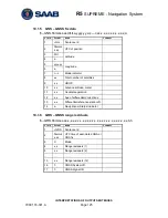
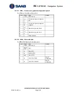
Page 135: ...s E W Used 4 a 5 x x Magnetic variation degrees E W Used 6 a 11 1 5 HDT Heading True HDT x x T Field Format Name Comment 1 HDG Sentence Id Used 2 x x Heading degrees true Used 3 T 11 1 6 RTE Routes RTE x x x x a c c c c c c Field Format Name Comment 1 RTE Sentence Id Used 2 x x Total number of messages being transmitted Used 3 x x Message number Used 4 a Message mode Used 5 c c Route identifier Us...

Page 136: ...ent 1 VHW Sentence Id Used 2 x x Heading degrees true Used 3 T 4 x x Heading degrees magnetic Used 5 M 6 x x Speed knots Used 7 N 8 x x Speed km h Not used 9 K 11 2 Input Sentences Old NMEA Versions 11 2 1 Rnn Routes old NMEA versions Can only be used for input of working active route It is recommended to use the RTE sentence instead if this sentence Per default any talker ID is accepted Rnn cccc ...

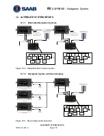
Page 137: ... Used in AIS and Combined System only USER 1 In Out USER 2 Out USER 3 In Out USER 4 In Out Speed Log Out 4xDigital I O Alarm Ack In Alarm Relay R5 NAV Sensor Cable External power 24 VDC R5 Signal Cable R5 Power Cable Figure 104 Redundant NAV interconnection 12 1 2 Navigation System with Slave Displays MASTER CDU Slave CDU Slave CDU Slave CDU R4 GPS Navigation Sensor or R4 DGPS Navigation Sensor US...

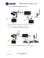
Page 138: ...the R5 NAV Junction box can be omitted if open cables for the CDU and Navigation sensor are used together with a customer own solution for interconnection of the system In addition to the standard R5 NAV parts the following are needed in addition Name Part number Qty R5 SUPREME Transponder 7000 118 100 incl AIS SW 1 0 X 7000 118 501 1 R5 Power Cable 2m 7000 118 077 1 R5 Signal Cable DSUB DSUB 2m 7...

Page 139: ...R5 NAV junction box 12 2 1 R5 Combined without R5 NAV Junction box VHF System Port User Port 1 User Port 2 Speed Log Alarm Output RS 422 Ports User Port 3 User Port 4 R4 Sensor Alarm ACK Binary Ports RS 422 Ports R4 Nav Signal and Power Cable R4 GPS Navigation Sensor or R4 DGPS Navigation Sensor 24 VDC 1A External fuse 24 VDC 5A External fuse Front Hatch USB Host SDHC Card Reader Pilot Plug Used i...

Page 140: ...S422 Green 4 In User Port 4 RxA RS422 Yellow 5 Out User Port 4 TxB RS422 Grey 6 Out User Port 4 TxA RS422 Pink 7 In User Port 3 RxB RS422 Blue 8 In User Port 3 RxA RS422 Red 9 User Port 3 GND RS422 Black 10 Sensor Port GND RS422 Violet 11 In Sensor Port RxB RS422 Grey Pink 12 In Sensor Port RxA RS422 Red Blue 13 User Port 4 GND RS422 White Green 14 Out General I O 1 Out Binary Brown Green 15 Out G...

Page 141: ...n Red 25 NOT CONNECTED 26 NOT CONNECTED Table 14 26 pin High Density D sub 13 1 1 3 Power port Pin In Out Signal Name Signal Type R5 Power Cable 1 In PWR 24 VDC Red 2 In PWG GND 0 VDC Black 3 Brown 4 Orange Table 15 CDU Power port 13 1 1 4 GND Screw M6 13 1 2 CDU Front hatch Figure 108 CDU Front ports 13 1 2 1 USB Host Type A USB 2 0 Supports FAT32 file systems and USB keyboards 13 1 2 2 CDU Pilot...

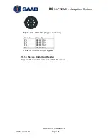
Page 142: ...142 Figure 109 CDU Pilot plug pin numbering Pilot plug Signal Type PIN 9 RS 422 GND PIN 1 RS 422 TX A PIN 5 RS 422 RX A PIN 4 RS 422 TX B PIN 6 RS 422 RX B Table 16 CDU Pilot port signals 13 1 3 Secure Digital Card Reader Supports SD and SDHC cards with FAT32 file systems ...

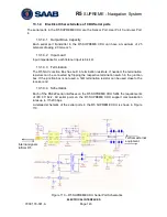
Page 143: ...ion Box has built in termination resistors If needed the termination resistors can be connected by flipping the respective termination switch in the junction box If the junction box is not used a 1kΩ termination resistor can be used close to the receiver end 13 1 4 4 Schematics Each of the RS422 serial interfaces on the R5 SUPREME CDU fulfils the requirements of IEC 61162 2 All serial ports on the...

Page 144: ...rt 1 TxB RS422 Pink 9 In Power GND 0 VDC Blue 10 Out System Port TxA RS422 Black 11 Out System Port TxB RS422 Purple 12 NC NC 13 Out User Port 2 TxB RS422 RTCM SC 104 Red Blue 14 In Alarm Ack In 0 VDC NC White Green 15 Out Speed Log Out 0 VDC 5VDC White Yellow 16 Out User Port 2 TxA RS422 RTCM SC 104 Grey Pink 17 In Power Vcc 12 24 VDC Red 18 Out Alarm Relay Out 0 V Active Vcc 1V Inactive White Gr...

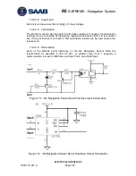
Page 145: ... termination switch in the junction box If the junction box is not used a 1kΩ termination resistor can be used close to the receiver end 13 2 3 4 Schematics Each of the RS 422 serial interfaces on the R4 Navigation Sensor fulfils the requirements as specified in IEC 61162 1 In addition User Port 1 supports a communication rate up to 38400 bps and User Port 2 up to 19200 bps Figure 111 R4 Navigatio...

Page 146: ...ng capacity of 10 mA Note Signal GND is internally connected to the negative power supply of the R4 Navigation Sensor 13 2 4 2 Alarm Acknowledge Binary Port The Alarm Ack In wire should be connected to Alarm Ack GND via a normally open momentary switch capable of handling a 1 mA current Note Alarm Ack GND is internally connected to the negative power supply of the R4 Navigation Sensor 13 2 4 3 Ala...

Page 147: ...nd ports M20 Will fit 6 12 mm cables For larger cables please unscrew the cable gland 13 3 2 External Power The R5 SUPREME Navigation System is designed to operate on 12 24 volts DC The R5 NAV Junction Box shall be connected to an emergency power source If connected to an emergency battery a re calculation must be made for the battery capacity To avoid power and voltage drops in the feed line it i...

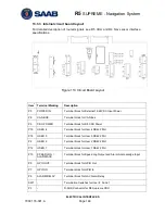
Page 148: ...nal block for CAN Bus P5 CDU POWER Terminal block for R5 CDU Power P19 USER 4 Terminal block for User 4 RS422 Port P18 USER 3 Terminal block for User 3 RS422 Port P2 USER 2 Terminal block for User 2 RS422 Port P12 USER 1 Terminal block for User 1 RS422 Port P10 SPEED LOG ALARM ACK Terminal block for Speed Log Output and Alarm Acknowledge Input P9 GPIO OUT Terminal block for GPIO Out P7 GPIO IN Ter...

Page 149: ... P4 D SUB Connector for R4 Navigation Sensor F1 5A fuse for CDU F2 1A fuse for Navigation Sensor Table 1 Terminals and Components Note 1 The item markings listed in Column 1 are not visible on the circuit board The terminal markings should be used when referring to terminals ...

Page 150: ...R5 SUPREME Navigation System MECHANICAL DRAWINGS 7000 118 301 A Page 150 14 MECHANICAL DRAWINGS 14 1 CDU Physical Size and Mechanical Drawing Figure 114 R5 SUPREME CDU Mechanical Drawing mm ...

Page 151: ...R5 SUPREME Navigation System MECHANICAL DRAWINGS 7000 118 301 A Page 151 14 2 CDU Panel Mount Cutout Hole dimensions ...

Page 152: ...R5 SUPREME Navigation System MECHANICAL DRAWINGS 7000 118 301 A Page 152 14 3 Sensor Physical Size and Mechanical Drawing Figure 115 R4 Navigation Sensor Measurements mm ...

Page 153: ...R5 SUPREME Navigation System MECHANICAL DRAWINGS 7000 118 301 A Page 153 14 4 R5 NAV Junction Box Physical Size and Mechanical Drawing Figure 116 R5 NAV Junction Box Dimensions mm ...

Page 154: ...OR COPYING DISTRIBUTION AND MODIFICATION 0 This License applies to any program or other work which contains a notice placed by the copyright holder saying it may be distributed under the terms of this General Public License The Program below refers to any such program or work and a work based on the Program means either the Program or any derivative work under copyright law that is to say a work c...

Page 155: ...satisfy both it and this License would be to refrain entirely from distribution of the Program If any portion of this section is held invalid or unenforceable under any particular circumstance the balance of the section is intended to apply and the section as a whole is intended to apply in other circumstances It is not the purpose of this section to induce you to infringe any patents or other pro...

Page 156: ...ome to redistribute it under certain conditions type show c for details The hypothetical commands show w and show c should show the appropriate parts of the General Public License Of course the commands you use may be called something other than show w and show c they could even be mouse clicks or menu items whatever suits your program You should also get your employer if you work as a programmer ...

Reviews: