ETHERLINK II - Repeater
Manual
Page 94 of 106
7 APPENDICES
7.1
Example 1 of configuration of Etherlink_II devices
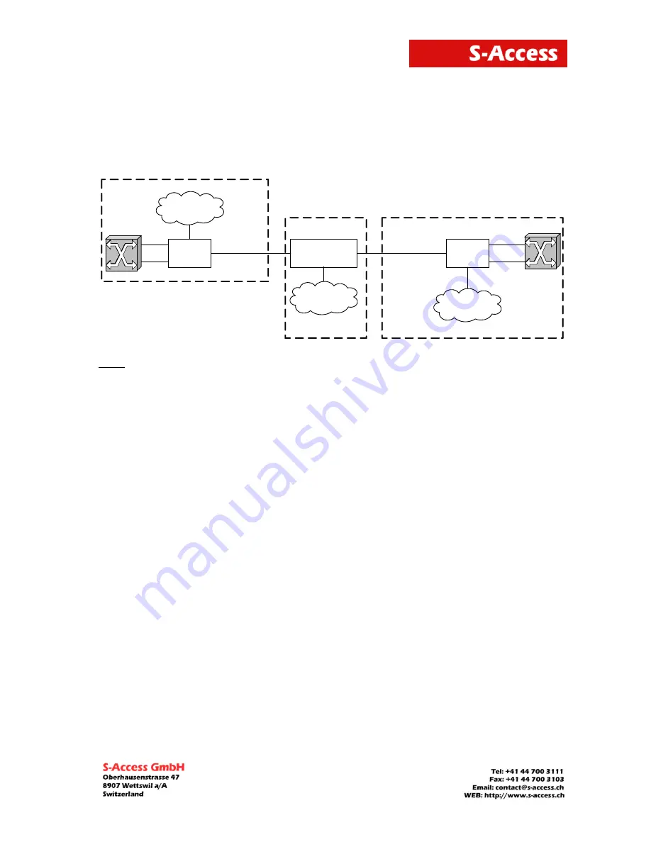
An example of organization of a data transmission system with the help of Etherlink_II devices
is presented below:
LTU
RGNo2
( remote power)
NTU
SHDSL
SHDSL
SA- PAM- SRL-2E1B/4 Eth-RP , V9
SA- PAM- SA2N-2E1B/Eth, V8
SA- PAM- RGN- Eth-PL , V8
G. 703 (E1-1)
Repeater Point
G. 703 (E1-2)
ATS
G. 703 (E1-1)
G. 703 (E1-2)
ATS
Ethernet
Network
ETH1
Ethernet
Network
Customer Premises Equipment
Central Office
Ethernet
Network
ETHERLINK II
ETHERLINK II
Note: The PABX (ATS in the figure) supports the CRC4 mode, if this mode is enabled. Before
setting IP addresses of the system devices, make sure that these IP addresses are not
used by other devices connected to the system. (Enter the PING command to check IP
addresses in all networks connected to the S-Access ETHERLINK_II equipment).
We present settings of the devices below. If all these settings are configured as shown below,
the user will construct a data transmission system, which will operate normally. The idea is as
follows: the default settings are deleted on all the devices, then the MASTER/SLAVE mode is
enabled on the modem, the network settings are configured (IP address, default subnet mask
and default gateway) and finally, these settings are applied and then are written in the
EEPROM.
7.1.1 Configuration of the S-Access Etherlink_II device at the Central Office premises.
System configuration (Configuration Management menu):
<DEFAULT EVERYTHING>
–
enable default settings
<POWER ON>
–
switch on remote powering (the modes are activated by jumpers
on the main board)
Line interface configuration (Configuration Management menu):
<MASTER ON>
–
enable the Master mode
Configuration of the internal Ethernet switch (Network Management submenu):
<SETIP 10.0.2.200>
–
set the IP-address of the device (depends on the configuration
of the network)
<NETMASK 255.0.0.0>
–
set the subnet mask (this value is the same as in the connected
Ethernet network)
<GATEWAY 10.0.0.101>
– set the default gateway (this value is the same as in the
connected Ethernet network)
Application of all configurations (Fault And Maintenance Management menu):
<APPLY ALL>
–
apply all configurations (written in the running configuration)
Confirmation of all configurations (Fault And Maintenance Management menu):
<CONFIRM>
–
confirm all configurations
(written in the startup configuration)


